February 08, 2018
20 Years Later: What’s New with 4L60-E PWM Modifications
Transmission builders are no strangers to modification. Making changes to increase performance, to prevent known issues from cropping up or to overcome existing problems is a hallmark of the ingenuity of the rebuilding industry. Many of these modifications can be beneficial, but some can cause unintended complications or downright damage.
Torque Converter Failure & TCC Friction Linings
There is a common modification for the 4L60-E TCC circuit that causes multiple problems, one of which is TCC friction delamination. Knowing how and why this happens is the key to avoiding converter failure comebacks which are the product of a modification someone else performed.
Before GM introduced its pulse width modulated (PWM) control system in the mid-1990s, the 4L60E TCC apply/release tactics were simple: on or off. At the appropriate moment, a command from the PCM to the TCC solenoid stroked the converter clutch valve, allowing release fluid to exhaust and opening the apply circuit for business. When the PCM de-energized the solenoid, the valve returned, allowing converter feed oil to switch back to the release circuit and cutting off apply pressure.
Simple and effective. But on/off operation had some shortcomings. Switching the TCC abruptly can result in a harsh apply sensation and adds unnecessary stress to driveline components. And while fuel economy improves with TCC operation, it can be increased further with a different control process. For these reasons the PWM control strategy was introduced. This control scheme eliminated the on/off feature in favor of a gradual apply/release function.
A second TCC solenoid was added to control the regulated apply valve. The TCC lining also was changed, from paper to a high-carbon content lining to stand up to the extra friction and heat generated during PWM operation. HTE (High Thermal Engaging) friction linings available from Sonnax are a good example of this type.
Under PWM control, the PCM sends a variable duty cycle to the second solenoid to control the regulated apply valve (Figure 1). The percentage at which the PCM increases or decreases the duty cycle controls the rate at which the TCC applies and releases. Ramping this pressure in stages gives us the smooth operation and improved fuel economy we’re looking for.
| Figure 1: OE Valve - Regulated TCC Apply |
|---|
 |
Figure 2 shows PWM progression during typical TCC application. Note the linear duty cycle change from 0% (unlocked) to 90% (full lockup), plenty of time to gently apply the clutch without harsh feel or driveline disturbance.
| Figure 2: 4L60-E PWM Application Sample |
|---|
 |
As a further effort to improve fuel economy and prolong the life of transmission and engine components, PWM control evolved into EC3. The valves and solenoids remain (virtually) the same as with PWM operation, but the control strategy and TCC lining have again undergone changes.
Within the EC3 game plan it is generally undesirable to fully lock the TCC. Instead, a consistent slip of about 20 to 40 RPM is aimed for under most operating conditions. It is because if this controlled slip that a different clutch material must be used. Friction material designed for use in on/off systems will burn up when subjected to modulated slip conditions, and the lining material designed for PWM control typically wears out prematurely if used in EC3 systems. A friction lining with higher thermal capacity must be used such as the HTS (High Thermal Slipping) linings offered by Sonnax.
Torque Converter Failure & TCC Apply Pressure
When the PCM determines EC3 clutch application is necessary, the duty cycle for the regulator solenoid is raised in rapid steps to around 50%, providing enough pressure for converter apply to begin. It is right around this 50% mark that our desired slip (20-40 RPM) is achieved under most driving conditions, and the PCM will constantly monitor and adjust the pulse width in an attempt to keep it in this window while the TCC is applied. Under some high-torque or freeway speed situations, the PCM will increase duty cycle to 98% to fully lock the TCC. This eliminates slip and prevents excess heat during high-load conditions.
This adaptive control strategy can provide nuggets of diagnostic gold: as the regulator bore wears, the duty cycle required to keep slip in the appropriate range increases. You often can spot TCC problems before they trigger codes by monitoring duty cycle with a scan tool. For example, if you have a vehicle with a few clicks on the odometer and an average TCC duty cycle of 79%, you can be pretty sure the PCM is compensating for circuit wear, most likely in the regulator bore.
A common problem with PWM and EC3 units is caused by continuous oscillation of the regulator valve, which creates bore wear over time that allows critical apply pressure to exhaust. This often results in the setting of code P1870 and/or P0894 due to excess TCC slip. Transmission builders quickly realized they could eliminate these codes (but not the bore wear that caused them) by blocking the regulator valve with an inner pump slide spring from a 700-R4, effectively returning it to an on/off system (Figure 3).
| Figure 3: OE Valve - TCC Reg. Valve Blocked for Full Line |
|---|
 |
This modification allows full line pressure into the apply circuit, up to 140 psi under load. In contrast, OE apply pressures range from about 60 to 80 psi. While the extra pressure masks bore wear and provides a Band-Aid for TCC slip, it can lead to:
- Cracked or deformed TCC pistons
- Broken damper rivets
- Torsional driveline disturbance
- Damaged crankshaft bearings
- Harsh apply feel
- Friction lining delaminating from TCC pistons (PWM and EC3)
- Converter failure
These problems are made worse if line pressure modifications are performed which allow even higher pressures into the apply circuit. On top of this, a sizeable line pressure leak is introduced, because the worn regulator bore is now open to line pressure, allowing it to bleed off to exhaust.
This blocking modification has been embraced by some builders of high performance or heavy towing units, even without a trouble code to conquer. There is at least one aftermarket kit that mimics blocking the valve, with the same detrimental high pressures being allowed to the apply circuit.
With this information in mind, it becomes apparent how a torque converter that was built perfectly to specification can fail due to being installed in an improperly modified transmission.
Sonnax TCC Pressure Limiter
To avoid the negative repercussions of full line pressure in this circuit while still allowing slightly elevated apply pressures for better performance, Sonnax developed the TCC pressure limiter spring system, which converts the TCC regulator valve into a simple pressure limit valve. With the isolator valve removed and the PWM feed orifice in the separator plate blocked, installing the limiter behind the regulator valve regulates line pressure into the apply circuit down to a maximum of 100 psi (Figure 4). This is enough for extra holding power while avoiding the consequences of full line pressure to the TCC piston. It’s the only available modification that both eliminates PWM/EC3 operation and limits converter pressure to acceptable levels. Since the apply pressures are capped in this manner, the pressure limiter can be used with friction linings designed for on/off, PWM or EC3 with great success.
| Figure 4: Sonnax Limiter Spring - TCC Apply Pressure Limited to 100 PSI |
|---|
 |
The pressure limiter is a performance-enhancing spring found in Sonnax’s popular HP-4L60E-01 Performance Pack that changes how the lockup system works. The spring is NOT a repair for a worn regulator bore, as it is designed to work in a properly functioning apply circuit. If the TCC regulator valve bore is worn, the only way to restore the valve bore and prevent pressure loss is to install Sonnax TCC regulator and isolator valve kit 77754-04K (OE apply rate) or 77754-03K (increased apply rate). The TCC pressure limiter spring works equally well in an un-worn original bore or with the Sonnax sleeve kits. Used with 77754-03K, the limiter will deliver higher levels of performance by allowing pressure of about 110 psi into the apply circuit. This is the maximum clamping power available without causing the negative results associated with full line pressure to the TCC.
Like it or not, modifications will always be a part of this business. Some of them can burn you, even when you weren’t the one that performed them. Working with transmission builders to ensure they are buying a 4L60-E converter with lining best suited to their particular build or modifications is one of the keys to long converter life and avoiding modification-related comebacks.
Learn More
Related Units
4L70-E Transmission
4L65-E Transmission
258mm LU (4L60-E, 5L40-E) Converter
280mm LU (4L60-E) “VJCX” Converter
300mm (4L60-E) Converter
4L60-E Transmission
245mm LU (3T40, 3L30, TH200C, 4T60-E, 4L60 & E:S-10 only) Converter
298mm LU (TH250C, TH350C, 200-4R, 4L60 & E) Converter
Related Parts
Required
Recommended
4L60-E, 4L65-E, 4L70-E
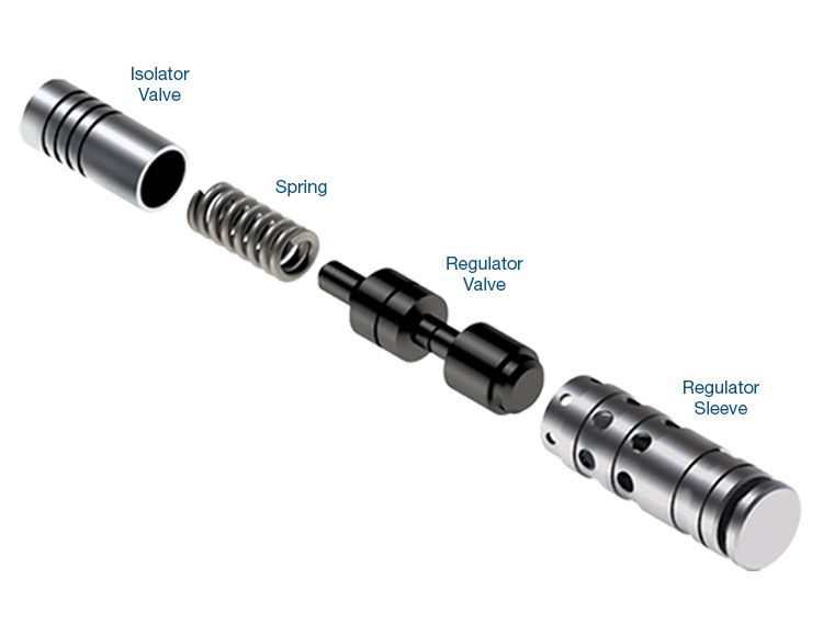
TCC Regulator & Isolator Valve Kit 77754-03K
4L60-E '97-earlier only, non-EC3 units
-
Helps cure:
- Code 894, 1870
- Overheated converter
- Low TCC apply pressure
- 3-4 Clutch burned
- 1-2 Harsh
- Low line pressure
Required
Recommended

4L60-E, 4L65-E, 4L70-E
TCC Regulator & Isolator Valve Kit 77754-04K
Fits all years & '98-later EC3 units
-
Helps cure:
- Code 894, 1870
- Overheated converter
- Low TCC apply pressure
- 3-4 Clutch burned
- 1-2 Harsh
- Low line pressure
Required
Recommended
4L60-E, 4L65-E, 4L70-E
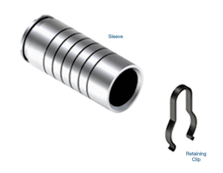
Isolator Sleeve Kit 77754-ISO
-
Helps cure:
- Code 894, 1870
- TCC cycling
- TCC slip
- 3-4 Clutch failure
While Sonnax makes every effort to ensure the accuracy of technical articles at time of publication, we assume no liability for inaccuracies or for information which may become outdated or obsolete over time.