Six Ways from Sunday: Diagnosing ZF6 & Ford 6R60/80 TC-Related Drivability Concerns
Bob Warnke
What is WK?
| Figure 1 |
|---|
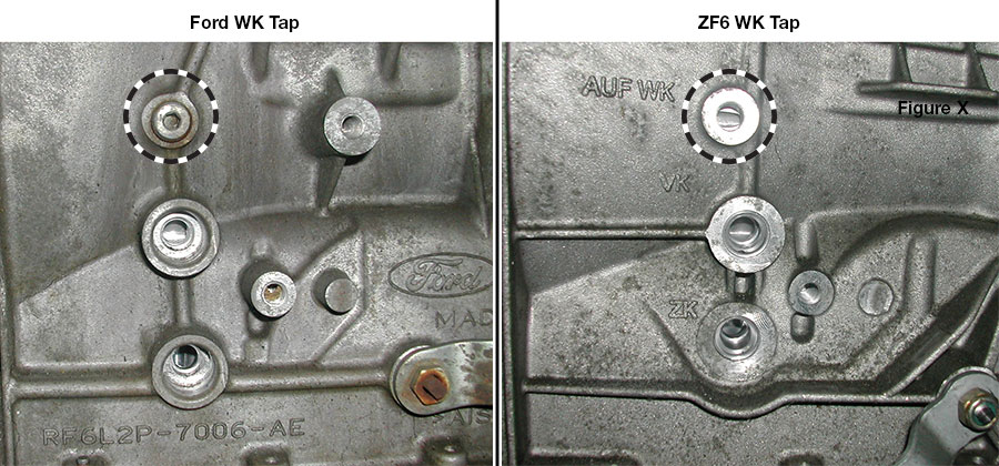 |
Accessing WK
Normal WK
| Figure 2 |
|---|
 |
Abnormal WK
- TC Slip
- Partial Release
- TCC/Solenoid/Ratio Codes
- Harsh Shifts
- Flare Shifts
- Rough Idle in Reverse
The Root Cause
A Ford Note
No Mechatronic Swapping Allowed
Bring It on Home
Related Units
Related Parts
Required
Recommended
6R60, 6R75, 6R80 (2009–2014), ZF6HP19, ZF6HP26, ZF6HP32
Oversized Pressure Regulator Valve Kit 95740-01K
Fits 6R80 '09-'14. Cannot be used in units that have a 053 separator plate.
OE valve name: SYS.DR-V
-
Helps cure:
- Poor shift quality
- Flare shifts
- Harsh shifts
- Erratic line pressure
- Slips in Forward & Reverse
- Delayed Reverse
- No Reverse
- TCC slip
Required
Recommended
6R100, 6R60, 6R75, 6R80 (2009–2014), 6R80 (2015-Later), ZF6HP19, ZF6HP21, ZF6HP26, ZF6HP28, ZF6HP32, ZF6HP34
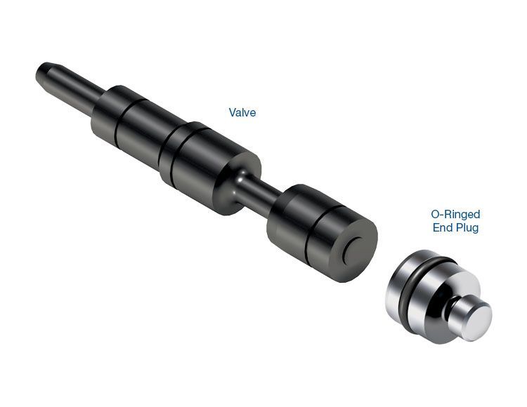
Oversized Converter Release Regulator Valve Kit 95740-05K
OE valve name: WK-V
-
Helps cure:
- Excess TCC slip RPM & related codes
- Harsh TCC apply & release
- Low TCC release pressure
- Rough idle in Reverse
- Harsh downshifts
- Flare shifts
- Overheated converter
Required
Recommended
6R100, 6R60, 6R75, 6R80 (2009–2014), 6R80 (2015-Later), ZF6HP19, ZF6HP26, ZF6HP32
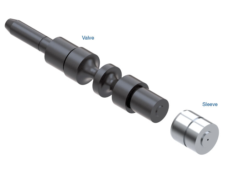
Oversized Lubrication Control Valve Kit 95740-11K
OE valve name: SCHM-V
-
Helps cure:
- Planetary failure
- Bushing failure
- Lube failures
- Overheating
- Low converter pressure
- Bump shifts
- Flare shifts
- Rough idle in Reverse
- TCC apply & release concerns
Required
Recommended
6R100, 6R60, 6R75, 6R80 (2009–2014), 6R80 (2015-Later), ZF6HP19, ZF6HP26, ZF6HP32
Oversized Bypass Clutch Control Valve Kit 95740-13K
OE valve name: WD-V
-
Helps cure:
- TCC codes
- Excess TCC slip
- Cycling RPM
- Low TCC release pressure
- Flare shifts
- Harsh shifts
- Rough idle in Reverse
- Overheated converter
Required
Recommended
6F35 (Gen. 1), 6F35 (Gen. 2), 6F35 (Gen. 3), 6R100, 6R140, 6R60, 6R75, 6R80 (2009–2014), 6R80 (2015-Later), 845RE, CFT30, ZF6HP19, ZF6HP21, ZF6HP26, ZF6HP28, ZF6HP32, ZF6HP34, ZF8HP45, ZF8HP55, ZF8HP70
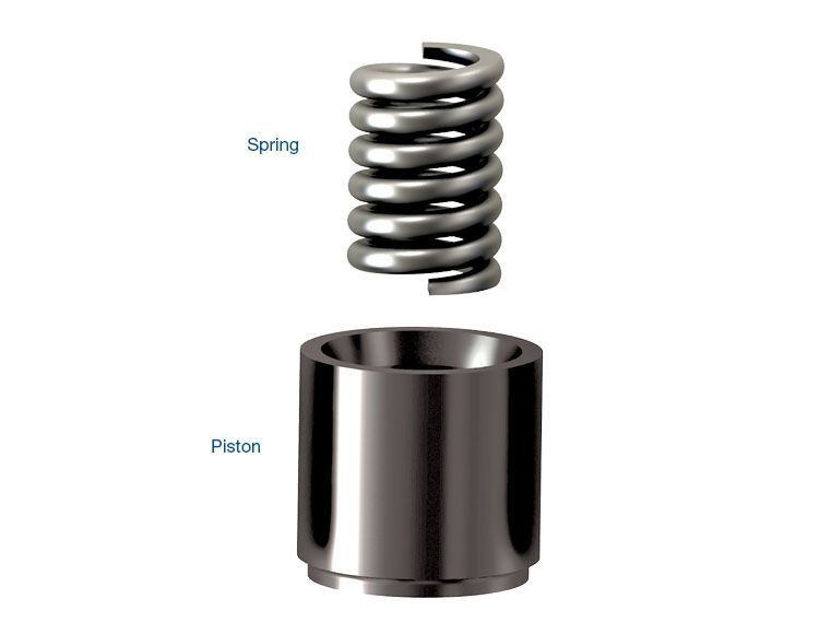
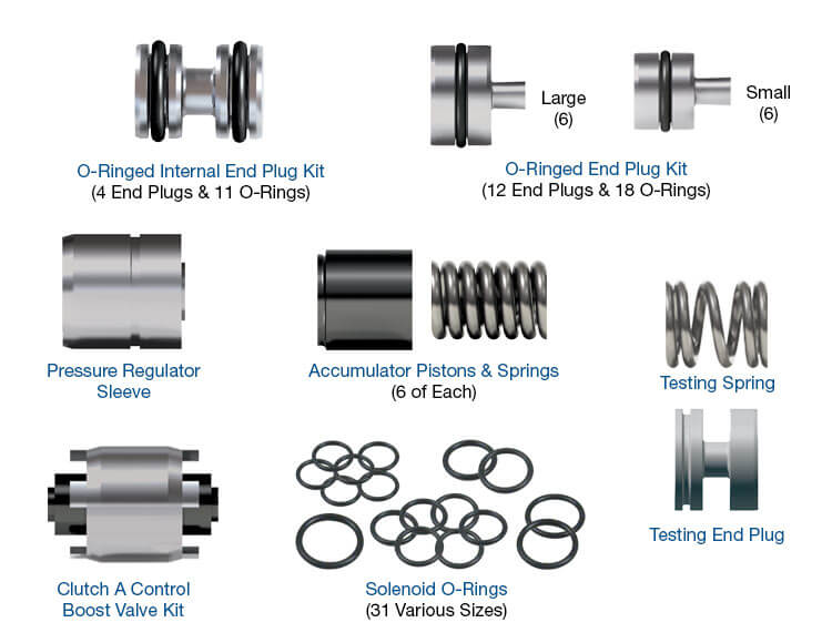
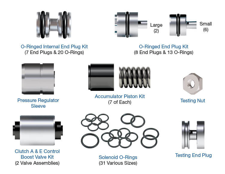
Accumulator Piston Kit 95740-15K
Required
Recommended
6R100, 6R60, 6R75, 6R80 (2009–2014), 6R80 (2015-Later), ZF6HP19, ZF6HP26, ZF6HP32
Oversized Solenoid Pressure Regulator Valve Kit 95740-17K
ZF valve name: DR.REO-V
-
Helps cure:
- Flare shifts
- Neutral shifts
- Harsh upshifts
- Harsh downshifts
- Gear ratio codes
- Solenoid performance codes
- Delayed Forward
- Delayed Reverse
- Wrong gear starts
- TCC slip
Required
Recommended
6R100, 6R60, 6R75, 6R80 (2009–2014), 6R80 (2015-Later), ZF6HP19, ZF6HP26, ZF6HP32
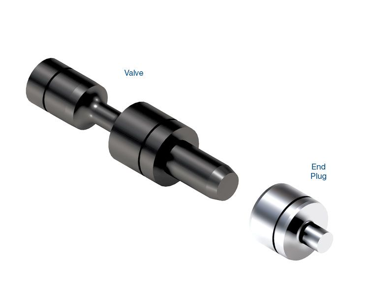
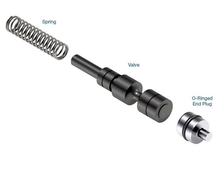
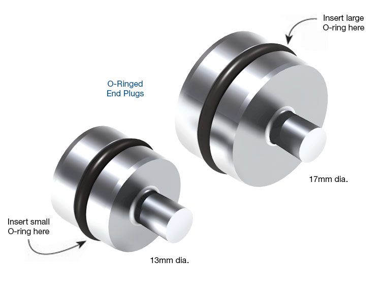
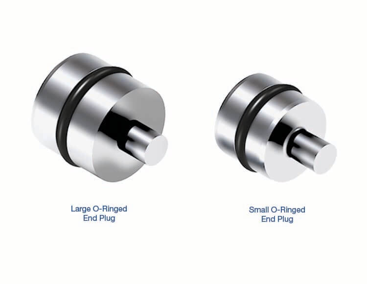
O-Ringed End Plug Kit 95740-19K
Required
Recommended
6R100, 6R60, 6R75, 6R80 (2009–2014), 6R80 (2015-Later), ZF6HP19, ZF6HP26, ZF6HP32
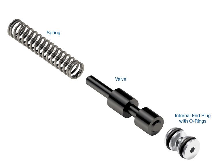
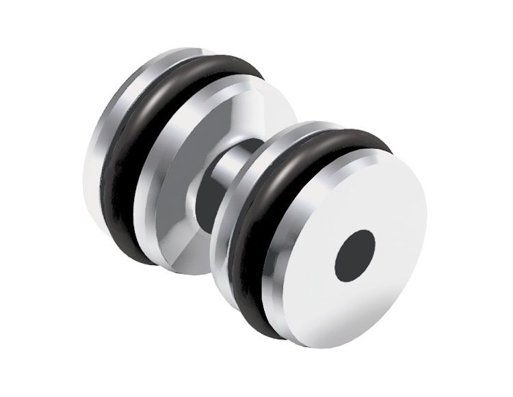
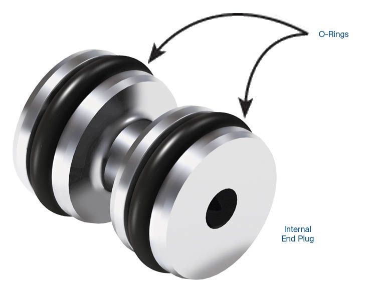
O-Ringed Internal End Plug Kit 95740-25K
Required
Recommended
Required
Recommended
ZF6HP21, ZF6HP28, ZF6HP34
Oversized Solenoid Pressure Regulator Valve Kit 95740-64K
ZF valve name: DR.REO-V
-
Helps cure:
- Delayed engagement
- Flare shifts
- Harsh downshifts
- Neutral shifts
- High line pressure
- Harsh upshifts
- Wrong gear starts
- Gear ratio & solenoid codes
- TCC slip
Required
Recommended
ZF6HP21, ZF6HP28, ZF6HP34
Oversized Pressure Regulator Valve Kit 95740-69K
ZF valve name: SYS.DR-V
-
Helps cure:
- Poor shift quality
- Low line pressure
- Flare shifts
- High line pressure
- Harsh shifts
- Burnt converter
- Delayed Reverse
- No Reverse
- TCC slip
Required
Recommended
ZF6HP21, ZF6HP28, ZF6HP34
Oversized Lubrication Control Valve Kit 95740-71K
ZF valve name: SCHM-V
-
Helps cure:
- Bearing failure
- Bushing failure
- Planetary failure
- Lube failures
- Low converter pressure
- Overheating
- TCC codes & concerns
- Rough idle in Reverse
Required
Recommended
6R80 (2009–2014), 6R80 (2015-Later), ZF6HP19, ZF6HP26, ZF6HP28
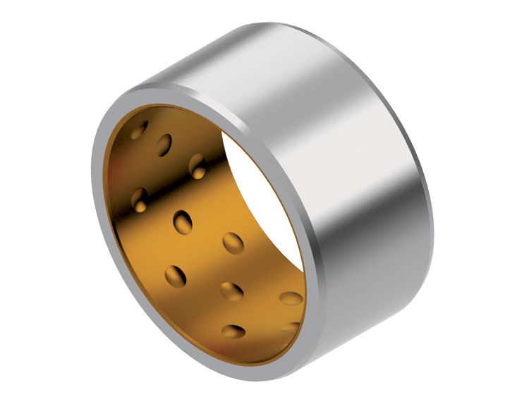
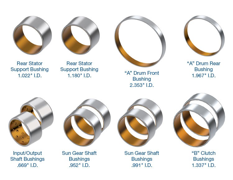
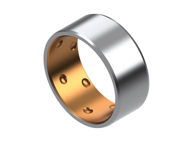
Input/Output Shaft Bushing 95030-05
Fits units with .669" (16.98mm) dia. shaft journals only.
- Bushing Style: Precision
- Material: Steel-backed alloy
- Housing Bore: 0.788"
- Shaft Dia.: 0.669"
- Width: 0.393"
-
Helps cure:
- Bushing wear
- Bushing failure
- Ratio codes
- B Clutch burned
Required
Recommended
ZF6HP19, ZF6HP26, ZF6HP32
Oversized Pressure Regulator Valve Kit 95740-78K
Fits units with 053 separator plate only.
OE valve name: SYS.DR-V
-
Helps cure:
- Broken parts due to excessive line pressure
- Erratic line pressure
- Harsh shifts
- High line pressure
- Restricted converter/lube flow
- Soft shifts
- Flare shifts
- TCC slip
Required
Recommended
6R100, 6R60, 6R75, 6R80 (2009–2014), 6R80 (2015-Later), ZF6HP19, ZF6HP21, ZF6HP26, ZF6HP28, ZF6HP32, ZF6HP34
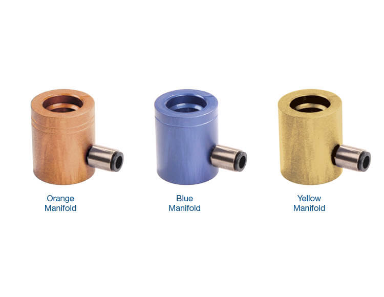
Solenoid Test Manifold Kit 95430-VTK
Required
Recommended
ZF6HP26, ZF6HP28
Bushing Kit 95030-26K
Fits units with input shaft bushing journal diameters of 1.022" (25.97mm) & 1.180" (29.96mm).
- Bushing Style: Precision
- Material: Steel-backed alloy
-
Helps cure:
- E Clutch burned
- B Clutch burned
- Gear ratio & solenoid codes
- Bushing wear
- Bushing failure
Required
Recommended
ZF6HP26, ZF6HP28
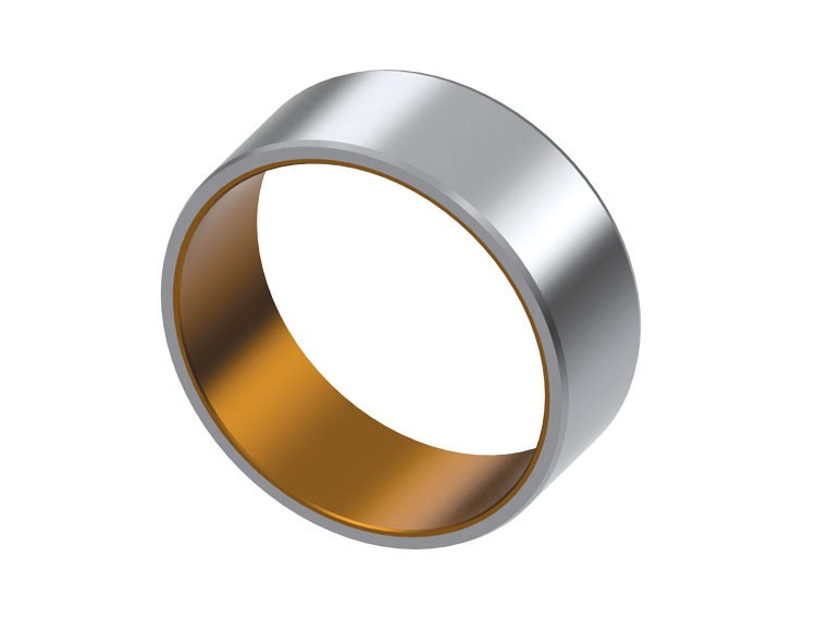
Sun Gear Shaft Bushing 95030-06A
Fits units with .991" (25.17mm) shafts only.
- Bushing Style: Precision
- Material: Bimetal
- Housing Bore: 1.103"
- Width: 0.394"
- Shaft Dia.: 0.991"
-
Helps cure:
- B Clutch burned
- Bushing wear
- Bushing failure
- Ratio codes
Required
Recommended
ZF6HP19, ZF6HP21
Sun Gear Shaft Bushing 95030-06B
Fits units with .833" (21.15mm) shafts only.
- Bushing Style: Precision
- Material: Bimetal
- Housing Bore: 0.953"
- Width: 0.394"
- Shaft Dia.: 0.833"
-
Helps cure:
- B Clutch burned
- Bushing wear
- Bushing failure
- Ratio codes
Required
Recommended
ZF6HP19, ZF6HP21
Sun Gear Shaft Bushing 95030-06D
Fits units with .904" (22.98mm) shafts only.
- Bushing Style: Precision
- Material: Bimetal
- Housing Bore: 1.024"
- Shaft Dia.: 0.904"
- Width: 0.394"
-
Helps cure:
- B Clutch burned
- Bushing wear
- Bushing failure
- Ratio codes
Required
Recommended

ZF6HP19, ZF6HP21
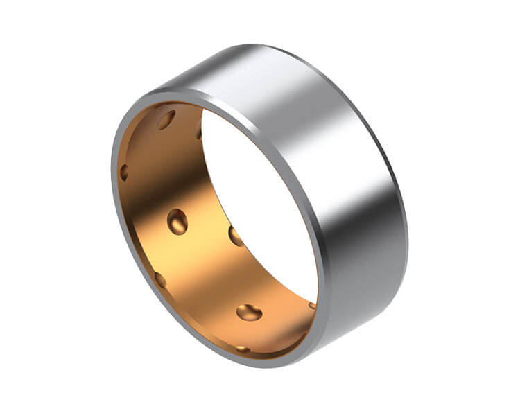
"B" Clutch Bushing 95030-07A
Fits units with 1.219" (30.97mm) shafts only.
- Bushing Style: Precision
- Material: Bimetal
- Housing Bore: 1.339"
- Shaft Dia.: 1.219"
- Width: 0.394"
-
Helps cure:
- Bushing wear
- Bushing failure
- B Clutch burned
- Ratio codes
Required
Recommended
ZF6HP19, ZF6HP21
Sun Gear Shaft Bushing 95030-06C
Fits units with .853" (21.68mm) shafts only.
- Bushing Style: Precision
- Material: Bimetal
- Housing Bore: 0.973"
- Shaft Dia.: 0.853"
- Width: 0.394"
-
Helps cure:
- B Clutch burned
- Bushing wear
- Bushing failure
- Ratio codes
Required
Recommended
ZF6HP19, ZF6HP21
"B" Clutch Bushing 95030-07B
Fits units with 1.396" (35.47mm) shafts only.
- Bushing Style: Precision
- Material: Bimetal
- Housing Bore: 1.516"
- Shaft Dia.: 1.396"
- Width: 0.394"
-
Helps cure:
- Bushing wear
- Bushing failure
- B Clutch burned
- Ratio codes
Required
Recommended
ZF6HP19, ZF6HP21
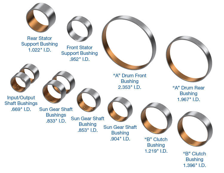
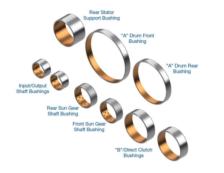
Bushing Kit 95030-19K
- Bushing Style: Precision
- Material: Bimetal
-
Helps cure:
- E Clutch burned
- B Clutch burned
- Gear ratio & solenoid codes
- Bushing wear
- Bushing failure
Required
Recommended
6R80 (2009–2014), 6R80 (2015-Later)
Bushing Kit 95030-80K
- Bushing Style: Precision
- Material: Steel-backed alloy
-
Helps cure:
- Bushing wear
- Bushing failure
- Ratio codes
While Sonnax makes every effort to ensure the accuracy of technical articles at time of publication, we assume no liability for inaccuracies or for information which may become outdated or obsolete over time.