January 05, 2015
Seal the Deal: How to Prevent Comebacks with Non-Valve-Body Vacuum Testing
Randall Schroeder
It is widely known that vacuum testing verifies wear levels in valve bores quickly and easily, helping to eliminate guesswork during diagnosis. Because of its effectiveness, vacuum testing has displaced less-reliable test methods to become the industry standard for identifying sources of valve body leakage. But are there other areas of the transmission — aside from the valve body — that could be tested for leaks using vacuum? Can this kind of testing make life on the bench easier by helping to identify “phantom” leaks that would otherwise result in costly comebacks?
Yes, and yes.
Tried & True
Vacuum testing is not a new process in the automotive field. After engine builders “lapped” a sealable mating surface between valves and their seats, they would use vacuum to test for any leaks that needed to be addressed. Vacuum testing is relatively new to the transmission rebuilding industry, though. Before this technique was introduced, conventional tests for bore wear included:
- Wiggle testing: Trying to detect bore wear by wiggling the valve in the bore.
- Wet air testing: Using low-pressure shop air to force fluid through the clearance between the valve and bore.
- Light transfer testing: Shining light through casting to see if light can be seen between valve and bore from other side of casting.
These tests are notoriously subjective; their accuracy and comparison to repeat tests performed after repairs could be interpreted as “test: passed” by one builder and “test: failed” by another. Being both accurate and repeatable, vacuum testing is a far superior technique that's become the new standard for identifying leakage within valve bodies. Unlike other methods, measuring the level of air that can be pulled through the clearance area between a valve spool and bore provides a numeric reading — on a gauge — that denotes how much wear has progressed. A high vacuum reading indicates minimal wear; lower vacuum readings indicate more clearance caused by wear. As you know, the clearance created by wear is the primary path for fluid under pressure to escape its circuit.
If we can pinpoint leaks in valve bodies, it makes sense that we can use vacuum testing to pinpoint the leaks outside the valve body that cause just as many drivability concerns and comebacks. Leaks can be identified while the unit is apart on the bench by testing the internal hydraulic circuitry that all automatic transmissions share. These tested areas include components such as:
- Checkballs
- Servos
- Accumulators
- Pumps
- Shafts to drums/housings
Tricks of the Trade
Perfect vacuum is measured at 29.92 in-Hg. However, depending on altitude, this number can change, so it’s necessary to calibrate the vacuum tester to your unique environment to obtain reliable readings. Part of the simple calibration procedure involves setting absolute vacuum to be represented by 25 in-Hg on the gauge. This means a reading of 25 in-Hg represents a “no leak,” a complete seal. In extreme altitude locations such as Denver, the max calibrated vacuum may only reach 22 in-Hg. That is OK, and that 22 in-Hg represents a full seal for that altitude. Whether the “no leak” value is 22 or 25, this is what you need to expect when testing something that should have zero leakage such as a checkball. Any number other than this sealed value represents a leak that must be fixed.
When it comes to testing parts (other than checkballs) that may have an acceptable amount of leakage, you must develop your own passable result standards. For instance, how do you know what a good number is when testing a servo pin bore or an assembled pump? The answer is to record a mix of results from known-good and known-bad components. For example, testing a known-good servo pin bore might return 18 in-Hg, while a known-bad bore might return only 10 in-Hg. By recording and referring back to your results, you will narrow your window of good versus bad and develop a minimum vacuum standard for a variety of different tests.
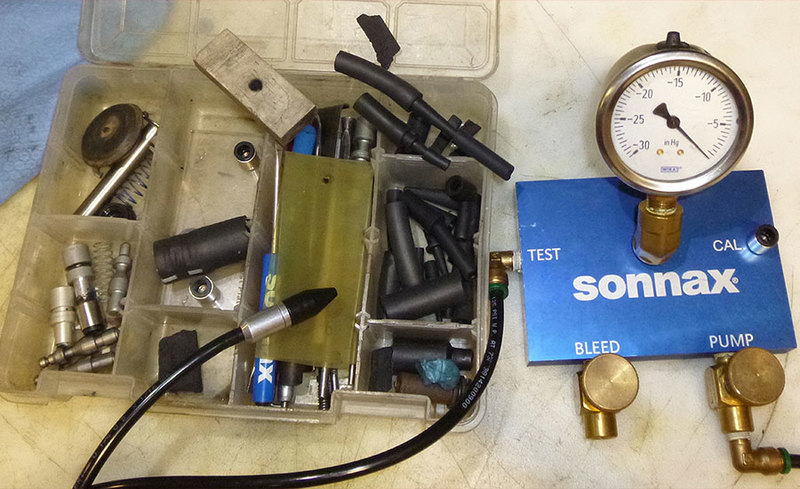
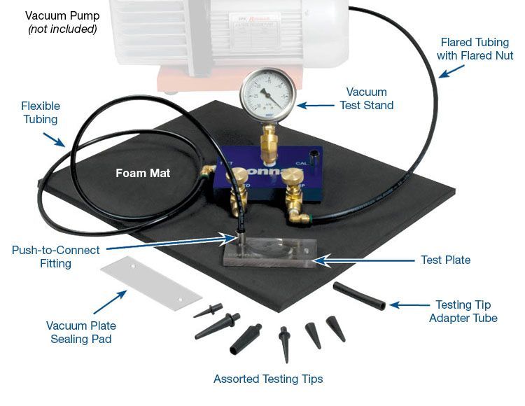
Another bit of legwork involves gathering some accessory items to facilitate testing, as you will not find “kits” that meet all your test needs. We all have lots of “home remedy” tools in our tool boxes, and vacuum testing is no different. Some useful accessories to have (Figure 1):
- Sample sizes of vacuum hoses — sometimes smaller hoses need to be installed into larger ones for tests.
- Thick rubber plugs — can be something as simple as a standalone pencil eraser.
- Rubber inner tubes from bicycles.
- Assortment of rubber pads to seal various portions of a circuit.
| Figure 1 - Some vacuum testing components you can buy, others you'll want to gather or make yourself so you have a handy tool kit for testing all kinds of transmission components. |
|---|
In your tool kit you will want different sizes of rubber tubes for testing. I asked a local bicycle shop for their throw-away inner tubes and got free tools! The list will grow as you figure out new ways to isolate and test individual circuits. If it can facilitate sealing or applying vacuum, you will find a use for it sooner or later.
An important part of implementing this type of testing is keeping the tooling readily available. If you have to search around the shop for the vacuum tester and accessories because they are scattered everywhere, you will often just skip the test and hope to dodge a bullet. If they are accessible on the bench, you will use them and avoid getting burned by repeat failures. Once you have the processes down, it only takes seconds to check the integrity of a seal. Always retest after any repair.
Checkballs
A checkball serves two purposes: to seal (when necessary) and to assist venting (when necessary). What the checkball is used for will determine which component(s) would fail, such as the band and 3-4 clutches in the 4L60/E when the 3rd accumulator checkball capsule in the case leaks — a common failure after repairs.
Some technicians will eliminate the ball and install a cup plug to prevent chronic leakage. No leak, no failure — or is this true? Remember, the ball is not only a seal for containing oil, it is a vent when air is needed to exhaust oil. When a plug is put into place, the vent is choked off, preventing necessary exhausting of the circuit. Replacing the 3rd accumulator ball with a cup plug often results in soft 2-3 shifts and 3-2 flares due to arrested venting.
It is common practice to test a checkball by shaking a drum or piston and listening for the sound of the checkball rattling. However, this only proves the ball can move; it proves nothing about sealing ability. Another test involves applying a thin-viscosity fluid around the ball, with a lightweight punch holding the ball against the seat. You would then observe whether there was fluid escaping to the opposite side of the ball, or if the level of fluid around the ball was leaking down. Unless the leakage is huge, this test is invalid. Without pressure, the ball will seal enough against a bad seat to prevent leakage. With the use of vacuum, pulling the ball against its seat provides an assessment that is easily viewed with numbers on a gauge — it is either sealed or not.
So how DO you properly test a checkball? For this example, we’ll return to the 3rd accumulator checkball capsule in 4L60/E. Use a pencil eraser or similar piece of pliable rubber that is drilled through to allow for the insertion of a rubber tip air nozzle attached to the vacuum gauge assembly. The other side of the eraser is held tight against the inside of the case where the passage to the exhaust side of the ball is located. Apply vacuum and verify that the gauge shows there is no leak (Figure 2).
| Figure 2 |
|---|
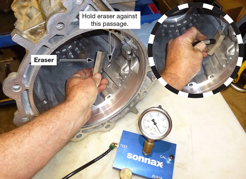 |
| Vacuum testing can be done simply and easily by holding the rubber tip air nozzle (inserted into a hole drilled in an eraser) up to the passage and checking the pressure reading. |
Leaks do not necessarily mean a part is bad; many parts that have been in-service and even new replacements often leak to some degree. In case of a checkball leak, use the following method to reform the seat into a sealable surface:
Choose the largest punch that will fit on top of the ball. The best tool is either a heavy plastic screwdriver handle or a ¾" wrench. You are going to lightly tap the punch — never use a hammer. Don’t hold the driver or wrench tightly; let it simply bounce in your hand like a drum stick as you lightly tap a few times on the punch to contour and fix the seat. Run your vacuum test again to verify that you have sealed the ball. If the checkball were in a solid housing, such as a cast-iron drum or an aluminum piston, you might be able to use a very small jeweler’s hammer to seat the ball for a retest. Be careful and gentle when reseating checkballs; it is easy to be too aggressive and damage the part you are trying to save.
Servos & Accumulators
Leaks at servo pin bores are common and cause comebacks when overlooked. Results can be burnt clutches, binding and/or flare shifts after repairs. Servo pin bore bushings are commonly used to repair leaks in bores where relentless cycling of the pin has worn the bore out. After reaming the pin bore and installing the bushing, a sizing tool is used to uniformly expand it in the bore. A servo pin is then inserted to verify it glides smoothly through the repaired bore. At this point, we would take for granted that the pin will seal well in the bushing since it slides easily. But easy movement only means the pin is free to move; it is no indicator of a good seal.
Accumulator pistons have similar wear problems due to cycling on the accumulator pin. When piston bore wear progresses enough, fluid begins to escape. Reinstalling a piston without first testing it for leakage between the pin and piston is asking for trouble.
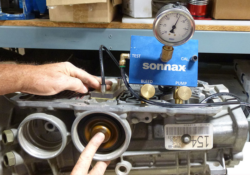
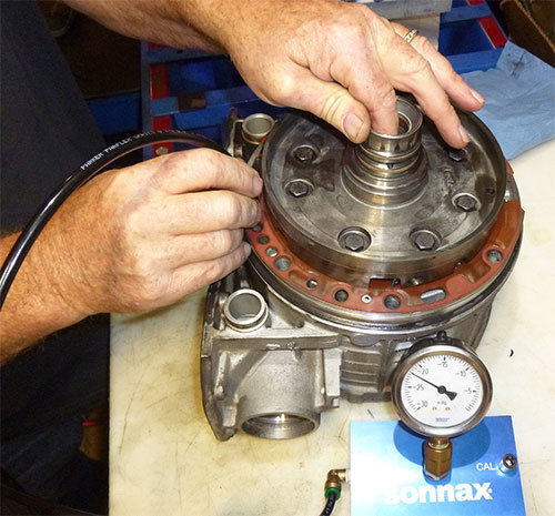
There are two simple methods for servo testing. One is to cover the case feed side with a test plate and plug the opening on the servo pin with your finger to gain a reading (Figure 3).
| Figure 3 |
|---|
The other method is to use a removable air nozzle tip to pull vacuum through the pin while blocking the top of the case with the test stand rubber pad. This also works with solid pins, though obviously there is no opening to plug.
For accumulators: with the piston installed, use an appropriately sized hose that covers the pin and piston bore together. Low vacuum numbers here betray a worn piston and/or pin.
Pumps
Various pump leaks and cross-leaks often result in symptoms that bring the vehicle right back into the shop. These can be frustrating: venting fluid, burnt clutches and binding during shifting, etc. Typically, problems are caused by warpage, cracks, twisted sleeves or gasket leaks. Sometimes there are self-induced failures during assembly that can cause leaks. For example, removing and pressing back in a stator support tube such as in the GM 4L60/E, or bolting in a replacement support tube such as those found in the GM 6L80 can leave unintended leaks. The capability of testing the pump before the unit is back in the vehicle is a critical advantage. Warpages that cause clutch fill issues and venting problems that lead to leaks are easily discovered when testing pumps with vacuum.
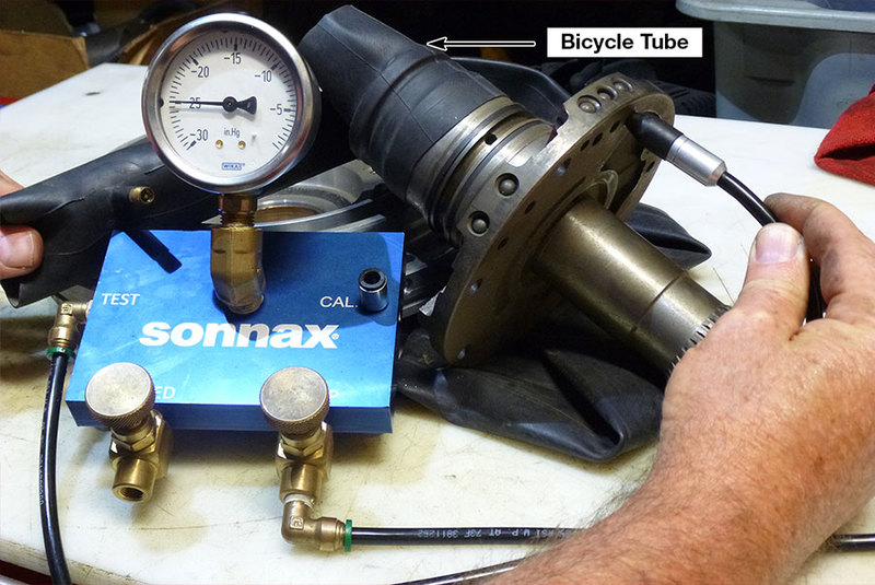
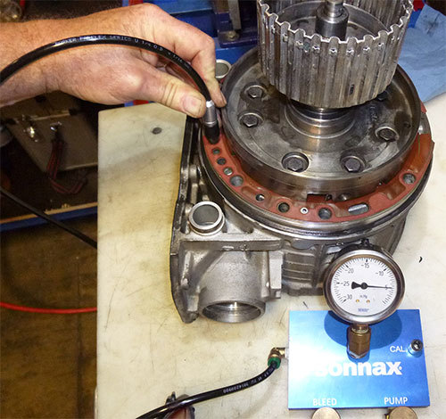
During pump testing, remember: oil in, oil out. To find out where to apply vacuum, a simple air test will show you where oil goes in and where it comes out of the assembly. The use of a bicycle inner tube makes easy work of sealing off areas that are being tested. When checking a single half support for core drill plugging — whether checkballs or cup plugs — and gaskets to housings, there must be no leakage (Figure 4).
| Figure 4 - A section of bicycle inner tube makes it easy to isolate pump areas during vacuum testing. |
|---|
When testing assembled halves, there will typically be small leaks and that is OK. As stated previously, you must determine what constitutes permissible leakage versus a leak that should raise alarms.
Shafts to Drums/Housings
Pressure loss at shaft/drum/hub interfaces is common due to the mating of different materials at critical circuit junctions. Through normal heating and cooling cycles, expansion and contraction results in high rates of leaks. When dealing with areas such as an input shaft to a drum or a drum feed through a bushing, testing is fast and accurate.
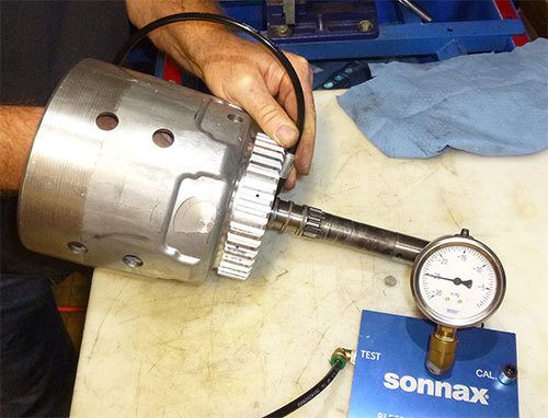
- Example 1: 4L60/E input drums — It is best to do this test (carefully) when the drum is hot so that the housing can expand and leaks will be easily found. Using a small rubber pad, block the piston feed hole inside the housing and use a rubber tip at the input shaft in the same manner you would to run an air test. There must be no leaks here (Figure 5). If leaks are present, the drum must be sealed or replaced.
| Figure 5 |
|---|
- Example 2: 4L30-E shaft to support bushing — The best tool for this job is a shaft removed/cut out of a core drum. The feed hole to the piston that was in the drum needs to be brazed or sealed with epoxy. First verify that the support to the O.D. section is perfectly sealed by bolting it in with the shaft removed. Check seal by applying vacuum to one side while blocking feed hole on other side (Figure 6).
| Figure 6 |
|---|
Once O.D. section seal is assured, insert the modified shaft into the bushing and note whether the vacuum reading meets your standards or betrays a failed bushing (Figure 7).
| Figure 7 |
|---|
The best method for setting standards here is to test a drum that showed no signs of failure; use this number as your minimum standard.
Winning the Battle
As you can see, the ability to unmask leaks outside the valve body with vacuum testing is not only achievable, it is a must-have weapon in your arsenal for fighting against comebacks. From checkballs to shafts and every hydraulic circuit in between, identifying and repairing internal leaks while the unit is apart on the bench is no longer a guessing game — thanks to the accuracy and reliability of vacuum testing.
Randall Schroeder is a Sonnax technical specialist and member of the Sonnax TASC Force (Technical Automotive Specialties Committee), a group of recognized industry technical specialists, transmission rebuilders and Sonnax Industries Inc. technicians.
Learn More
January 05, 2015
How to Vacuum Test Video - Part 3 of 3
January 05, 2015
Vacuum Test Stand Setup & Calibration Video - Part 2 of 3
March 18, 2021
Transmission Testing & Repairs: It’s NOT Business as Usual, so Make Sure You’re Vacuum Testing
Randall Schroeder
Related Parts
Required
Recommended
Vacuum Test Stand Kit VACTEST-01K
-
Helps cure:
- The need for a quick, easy & repeatable method to test valve & bore wear
While Sonnax makes every effort to ensure the accuracy of technical articles at time of publication, we assume no liability for inaccuracies or for information which may become outdated or obsolete over time.