Identifying Allison 1000/2000/2400 Valve Bodies
Over the years, the Allison 1000/2000/2400 valve body has had four versions. This article is written to help identify each version. The first two versions are 5-speed and the last two are 6-speed valve bodies. The information will explain casting number and separator plate combinations that work correctly together.
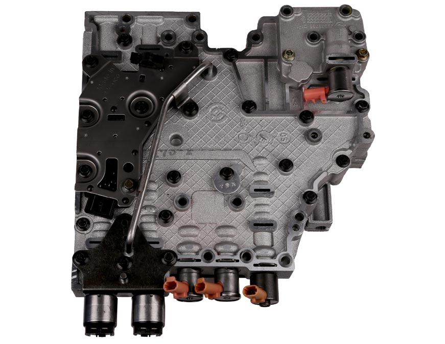
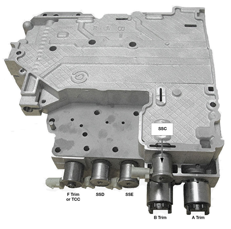
2001–2003 (5-Speed)
- Upper casting #29536838 (smaller section)
- Lower casting #29536840 (larger section)
- Spacer plate #7440
- Identifiers: This valve body has six solenoids, one tube on the bottom and two sections (Figures 1 and 2).
| Figure 1 | Figure 2 |
|---|
 | 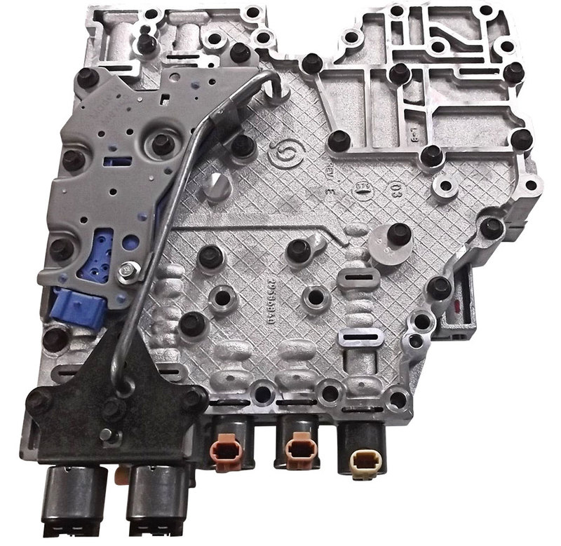 |
2004–2005 (5-Speed)
- Upper casting #29539798, and we have also seen 29541592 (smaller section)
- Lower casting #29539802 (larger section)
- Spacer plate #9793
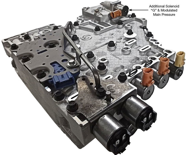
- Modulated main pressure housing casting #29539796 (smallest section that bolts onto the lower section and houses the solenoid G). The housing for the ‘04-‘05 does not have a hole for the second tube, nor does it use a second tube (Figure 3).
- Identifiers: This valve body has an additional small section with a seventh solenoid. The additional solenoid is designated as solenoid G, and is used to reduce line pressure at idle and during light throttle cruising speeds (Figure 4).
| Figure 3 | Figure 4 |
|---|
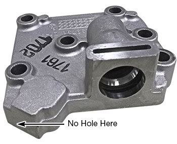 |  |
| Modulated main pressure housing with no hole for tube fits ‘04-‘05 5-speed transmission. |
|
2006–2009 (6-Speed)
- Upper casting #29542971 (smaller section)
- Lower casting #29543340 (larger section)
- Spacer plate stamping #2962, the GM part number is 29542962
- Modulated main pressure housing casting #29539796. This is the smallest section that the G solenoid fits into and has a hole in the corner for the tube (Figure 5).
- Identifiers: The 5-speed valve bodies always had a reverse tube on the bottom of the valve body. The 6-speed has an additional tube from the modulating main pressure housing to the lower casting (Figure 5). The 6-speed also has a different TCC solenoid with a red plastic electrical connector and different PCS-1 and PCS-2 solenoids.
- ‘06-‘09 Internal harness GM part number is 29543334
The casting number for the modulated main pressure housing for the ’04–’05 5-speed is the same as the casting number for the
’06–’09 6-speed. The only difference between the housings is the ’06–’09 6-speed version has a hole for the tube and the 5-speed does not.
| Figure 5 |
|---|
 |
2010–Later (6-Speed)
This valve body was totally redesigned for 2010 and will not interchange with any previous years.
- Fully variable modulated main pressure was a new feature for 2010.
- The castings were redesigned to accept new valves and feature new worm tracks.
- Shift valves SV1, SV2 and SV3 and the control main valve were redesigned.
- The PCS1 and PCS2 valves, solenoids and solenoid brackets were redesigned.
- Upper body casting #29550905
- Lower body casting #29550908
- The separator plate was redesigned and the new part number is 29545980. The plate is stamped with the last four digits of the part number, “5980.”
- The SS1, SS2 and SS3 solenoids are all etched with the number 6833.
- PCS-1 and MMS solenoids both have a black plastic electrical connector and the number 29541895 on the side of the solenoid can.
- PCS-2 solenoid has a brown plastic electrical connector and the number 29541896 on the side of the solenoid can.
- TCC solenoid has a red electrical connector and the number 29541898 on the side of the solenoid can.
- The internal harness was changed and the GM part number is 29545308.
- Identifiers: There are NO TUBES on the bottom of the valve body. There is no longer a modulated main pressure housing, and solenoid G has been eliminated. Solenoid G was replaced by the main modulator solenoid, which is a PWM solenoid (Figures 6 and 7).
| Figure 6 | Figure 7 |
|---|
 |  |
At a Glance
To quickly identify which version of the Allison 1000/2000/2400 valve body you have:
- ‘01-‘03: 5-speed, one tube on the bottom and six solenoids
- ‘04-‘05: 5-speed, one tube on the bottom and seven solenoids
- ‘06-‘09: 6-speed, two tubes on the bottom and seven solenoids
- ‘10-‘15: 6-speed, no tubes on the bottom and seven solenoids
Common Valve Body Problems
- The most common problem with the ‘01-‘09 Allison 1000/2000/2400 valve bodies is the sticking E-shift valve, or as it is called on the ‘06-‘09 6-speeds, shift valve 3. On the inboard end of the bore, the bore becomes damaged and causes the valve to stick. When this valve sticks — even for a split second — the TCM sees that the pressure switch does not change state, it sets trouble code P0872 and the transmission goes into failsafe. The maddening part of this is that the valve can be free one minute and stuck the next. There is now an oversized valve and reamer kit to fix this so that it will not stick again. The new oversized E-shift valve will work in the 5-speeds and the ‘06-’09 6-speed.
- The second most common problem is the F-trim valve sleeve. The inside diameter of the sleeve wears, causing TCC surge, TCC slip and trouble code P0741 – TCC slip. When lockup stops working and the P0741 code sets, the torque converter can overheat the transmission fluid, causing damage to the torque converter and rapid deterioration of the transmission fluid. The F-trim valve sleeve is only used from ‘02-‘04.
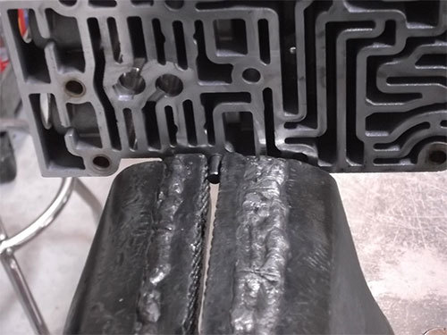
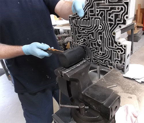
- The third most common problem is warped castings. These valve bodies do not use separator plate gaskets, except for the ‘10-later, so it is imperative that the two valve body halves be flat sanded to avoid cross-leaks. The dowel pins will need to be removed to flat sand this valve body. The dowel pins can easily be removed if you have a vise and a rubber mallet. Gently snug up the vice on the dowel pin (Figure 8). This will take a little trial and error to learn how tight to tighten the vice. Then use a rubber mallet to tap on the valve body to separate the valve body from the dowel pin (Figure 9). Don’t forget to hang on to the valve body!
| Figure 8 | Figure 9 |
|---|
 |  |
Caution: Only use a soft-face hammer and GENTLY tap on the valve body face. After removing the dowel pins, they may be a little distorted. Use a file to remove any marks that were made by the vice. The ‘10-later 6-speeds have been holding up well. Currently there are no common problems with this new design.
Jeff Parlee is the Sonnax remanufactured valve body product support manager and member of the Sonnax TASC Force (Technical Automotive Specialties Committee), a group of recognized industry technical specialists, transmission rebuilders and Sonnax Industries Inc. technicians.