October 28, 2014
Under Pressure: Shift Quality & Pressure Switches in TEHCM Applications
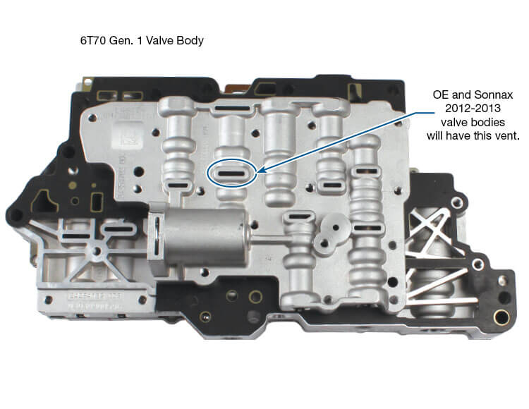
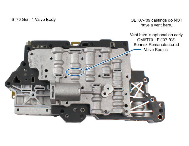
GM Generation 1 6T40/6T45/6T50 and Generation 1 6T70/6T75 automatic transmissions are each equipped with four pressure switches in the TEHCM (transmission electro-hydraulic control module) that is attached to the valve body (Figure 1). These pressure switches serve two primary functions: providing the computer with the gear selection and with clutch timing information.
| Figure 1 | Figure 2 |
|---|---|
 |
 |
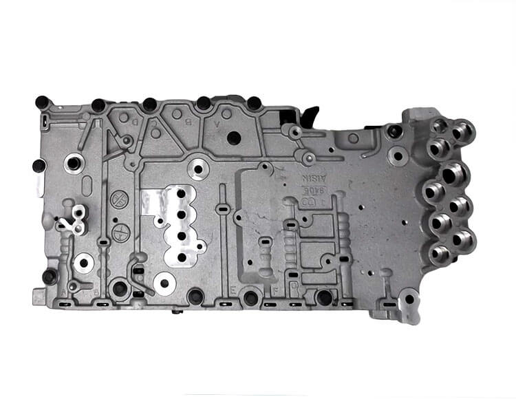
| Disassembled Gen.1 6T40 , late-design pressure switches. |
During a rebuild, failed pressure switches often can be detected by waffled or delaminated films. |
The gear selection data is determined by the open or closed nature of the pressure switches, which are each hydraulically tied to a clutch and regulator valve. The computer measures clutch timing by monitoring the movement of the pressure switch and input speed sensor changes. Since the clutch apply pressures are modulated, this feedback helps the computer monitor clutch wear over time and adapt the timing accordingly.
Pressure Switch Failure
When functioning smoothly, these pressure switches are a huge benefit to shift quality. Unfortunately these pressure switches have a significant failure rate, and have previously required the purchase of a new TEHCM for repair. Typically when a pressure switch fails, one or more of the following DTC's will set: P0752, P0872, P0877 and/or P0989. The vehicle might also go into limp mode.
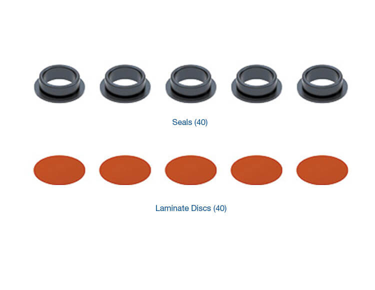
During a rebuild, failed pressure switches often can be detected by waffled or delaminated films (Figure 2). This can be caused by high pressures and/or debris, which then compromises the sealing and protecting nature of the film, exposing the piston and contacts to contaminants.
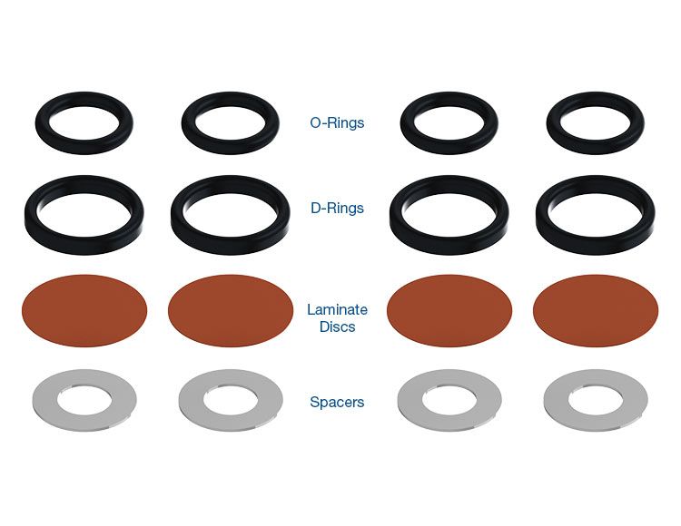
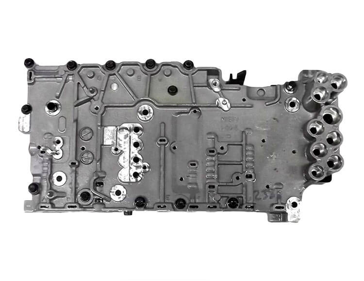
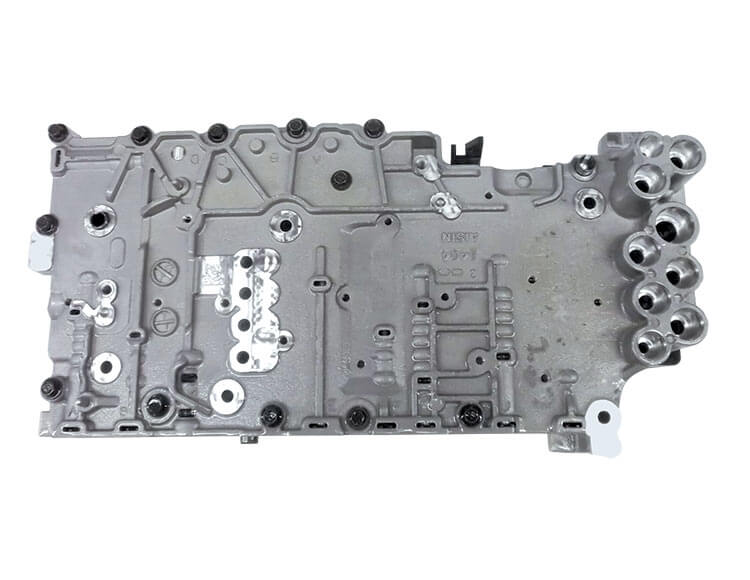
The Gen. 1 6T40 series has an early and late design (Figure 3) of these pressure switches, while the Gen. 1 6T70 series has one design. All three designs are normally-closed, allowing current to flow through the switch when not applied by fluid pressure. As fluid is directed to the switch, the film is pushed down against the piston and metal disc, separating the upper and lower contacts to prevent current flow. So if the seal and/or film have failed, it is easy to see how debris can enter the switch area and prevent proper contact operation.
| Figure 3 |
|---|
 |
Sonnax offers pressure switch film and seal kits for both the Gen. 1 6T40 series (144510-09K) and Gen. 1 6T70 series ([124740-28K], [124740-30K], [124740-TL30]) so that repairs can be made instead of replacing the expensive TEHCM.
The Elimination of Pressure Switches
The fluid pressure is supplied to each of these switches by hydraulic routing through the four different clutch regulator valves (1-2-3-4, R1/4-5-6, 2-6, and 3-5-Reverse).
| Figure 4 |
|---|
 |
| 6T40 Series Gen. 1 Clutch Regulator Valves & Oil Circuits, 1st Gear |
The primary purpose of each of these valves is to stroke in response to solenoid signal pressure and regulate drive/line fluid pressure into the associated clutch apply circuit (Figure 4). The secondary function of each of these clutch regulator valves, when in the rest or un-stroked position, is to direct fluid pressure to the pressure switch, which opens the switch and tells the computer that the clutch is in the released position. Thus in operation, the computer can detect which gear is selected by which switches are open or closed (Figure 5).
| Figure 5 |
Gear Selector Position |
Gen. 16T40 Pressure Switches |
Gen. 16T70 Pressure Switches |
||||||
|---|---|---|---|---|---|---|---|---|
| 1 | 2 | 3 | 4 | 1 | 2 | 3 | 4 | |
1-2-3-4 |
2-6 |
3-5-R |
R1/4-5-6 |
1-2-3-4 |
3-5-R |
2-6 |
R1/4-5-6 |
|
| Park | x | x | ||||||
| Reverse | ||||||||
| Neutral | x | x | ||||||
D1 Engine Braking |
x | x | x | x | ||||
| D1 | x | x | x | x | x | x | ||
| D2 | x | x | x | x | ||||
| D3 | x | x | x | x | ||||
| D4 | x | x | x | x | ||||
| D5 | x | x | x | x | ||||
| D6 | x | x | x | x | ||||
| Figure 5 - X = Clutch regulator valve is pressurized (open). The computer can detect which gear is selected by which switches are open or closed. | ||||||||
Beginning in 2012 model year for 6T40 series, and 2013 model year of 6T70 series transmissions, major changes were made which included elimination of these pressure switches. This was not a comprehensive change for all models, so RPO codes should be checked against GM bulletins to determine if your make/model/year has been updated to the new Gen. 2 transmission and TEHCM. Affected parts do not interchange between Gen. 1 and 2.
In regards to the TEHCM, looking at the middle number under the bar code on the TCU cover is a quick method for determining if it is a Gen. 1 or 2 (Figure 6). Additional identification information can be found in the Sonnax identification guides for each specific transmission.
| Figure 6 |
|---|
 |
| TEHCM ID Plate |
The updated TEHCM now uses “clutch pulse learning” to monitor shift timing and clutch wear. In this process, at approximately every 1,250 miles the computer pulses clutches on when not in use for the current power flow and determines changes in apply time. As a result of the Gen. 2 changes, the clutch regulator valves no longer need to perform their secondary function of routing the fluid to the (now eliminated) pressure switches. So the complexity of these valves is now simplified, reducing cost as well.
A comparison of Gen. 1 (Figure 4) and Gen. 2 (Figure 7) clutch regulator valves and oil circuits in the 6T40 shows the changes and that they are not interchangeable. Similar valve changes also were made in the 6T70 series transmissions.
| Figure 7 |
|---|
 |
| Gen. 2 6T40 Series Clutch Regulator Valves & Oil Circuits, 1st Gear |
Prior to rebuilding, make sure you have identified whether your unit is a Gen. 1 or Gen. 2 before making any valve body updates. A similar pressure switch design with similar associated problems is used in the 6L45–6L90 family. [124740-28K], [124740-TL30], and [124740-30K] fit 6L Series as well as Gen. 1 6T70 Series.
Learn More
Related Units
6T70 (Gen. 1) Transmission
6T75 (Gen. 1) Transmission
6L50 Transmission
6L45 Transmission
6L90 Transmission
6T50 (Gen. 1) Transmission
6T40 (Gen. 1) Transmission
6T45 (Gen. 1) Transmission
6L80 Transmission
Related Parts
Required
Recommended
6T30 (Gen. 1), 6T40 (Gen. 1), 6T45 (Gen. 1), 6T50 (Gen. 1)
Pressure Switch Rebuild Kit 144510-09K
-
Helps cure:
- Pressure switch codes
- Pressure control out-of-range codes
- Failsafe mode
- Slips, flares & bind-ups
- Harsh shifts
- Shift codes

Required
Recommended
6T70 (Gen. 1), 6T75 (Gen. 1)
Remanufactured Valve Body GM6T70-1L
Fits '09-'13 units with 1.83 ratio 3-5-R clutch regulator valve. Sold without TEHCM.
Required
Recommended
6T70 (Gen. 1), 6T75 (Gen. 1)
Remanufactured Valve Body GM6T70-1E
Fits '07-'08 units with 1.35 ratio 3-5-R clutch regulator valve. Sold without TEHCM.
Required
Recommended
6L45, 6L50, 6L80, 6L90, 6T70 (Gen. 1), 6T75 (Gen. 1)
Pressure Switch Rebuild Kit 124740-70K
-
Helps cure:
- Pressure switch codes
- Switch codes
- Pressure control out-of-range codes
- Slips, flares & bind-ups
- Failsafe mode
- Erratic TCC apply
- Harsh shifts
- Shift codes
Required
Recommended
6L45, 6L50, 6L80, 6L90, 6T70 (Gen. 1), 6T75 (Gen. 1)
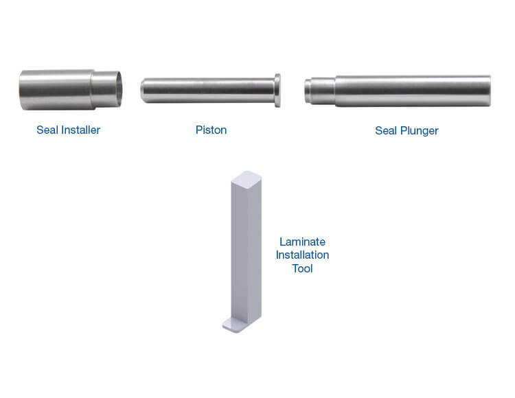
Pressure Switch Rebuild Installation Tool Kit 124740-TL70
While Sonnax makes every effort to ensure the accuracy of technical articles at time of publication, we assume no liability for inaccuracies or for information which may become outdated or obsolete over time.