November 20, 2020
Hydraulics Fundamentals Part I: Main Pressure Regulator Valve Line-Ups
Zachary Richardson
As today’s transmissions continue to increase in complexity, from growing involvement in electronic controls to a seemingly exponential increase of available gear ratios, one concept remains the backbone of automatic transmissions: hydraulics. Forces, pressures and flow rates are critical considerations in all stages of a transmission’s lifecycle. Engineers use these as tools to achieve desired shift timing, shift quality and overall efficiency. As rebuilders, it is important to understand hydraulics in order to properly diagnose failures and determine the best method to fix the transmission. As an aid in that regard, this will be the first in a series of Sonnax articles exploring how the different types of valves and hydraulic circuits work and (just as importantly) what symptoms or failures occur when they quit functioning correctly.
One critical “tool” that technicians can use in the real world to diagnose drivability concerns, trouble codes or internal failures is the knowledge that all hydraulic designs rely on a system’s ability to hold pressure. As vehicle mileage increases and components wear, hydraulic circuits begin to lose this ability. While there are a variety of hydraulic components in a transmission, the valve train can often be overlooked or misunderstood.
One of the most significant components is the main (or primary) pressure regulator valve. There are five pieces to how it regulates main line pressure and provides converter feed: source pressure, spring force, balance oil, an exhaust and opposing throttle signal/EPC fluid force (Figure 1).
| Figure 1 |
|---|
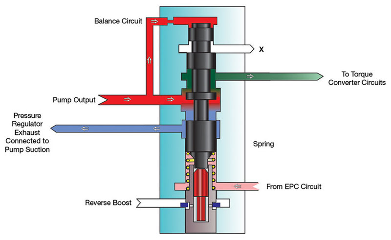 |
Pressure and volume flow directly from the pump is not consistent due to constant changes in engine speed, so unregulated pump pressure cannot be relied on for operating the transmission by itself. The pressure regulator valve is the equalizer and uses the pump to generate source pressure.
The pressure regulator spring is used to apply force to one side of the valve, and the spring design is a determining factor in what line pressure will be regulated to. This is because the spring force is constantly applied and pushing the valve to one end of the bore. There needs to be a greater force applied in the opposite direction of the spring in order to move the valve out of its resting position.
A balance system is fluid pressure applied to a reaction area on the valve to work against spring force and begin to move the valve into its regulating position. This is often regulated line pressure directed through an orifice to the balance spool. As the balance circuit is charged, a feed passage is opened to provide fluid flow to the torque converter and — indirectly — the lube circuit.
An exhaust passage is placed in the bore to dump off line pressure when the valve strokes far enough against the spring. At this point, the balance pressure drops due to the drop in line pressure, and the spring force moves the valve in the opposite direction. Without an exhaust passage, line pressure would essentially follow unregulated source pressure from the pump.
Throttle signal/EPC pressure is used to position the main pressure regulator valve in the bore to control the line pressure according to driving needs. At heavier throttle, or in Reverse, higher line pressure is required for increased torque and holding power, so a pressure “boost” is applied to the pressure regulator valve to move it to a high line pressure position. Some applications apply this pressure directly to the pressure regulator valve, some use a boost valve and sleeve assembly, and others use a combination of the two.
This line pressure adjustment can occur thousands of times in a drive cycle, making the main pressure regulator valve and associated boost valve assembly some of the most active valves in the transmission.
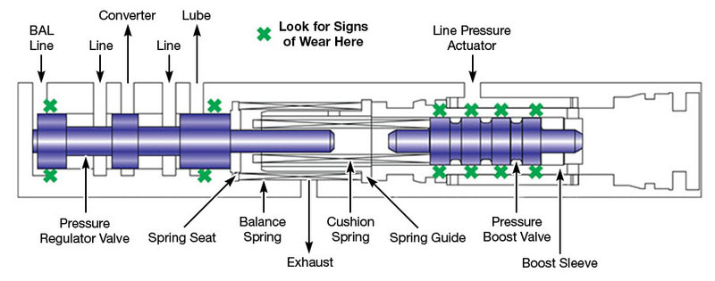
Due to constant movement in the bore, the main pressure regulator valve tends to be one of the most common wear areas inside any unit. An important consideration is the fact that symptoms will be different depending on what area of the bore is worn. Wear on the balance end can allow balance pressure to cross leak and requires higher line pressure to counteract the force of the PR spring. This is often seen in the Saturn TAAT valve bodies (Figure 2).
| Figure 2 |
|---|
 |
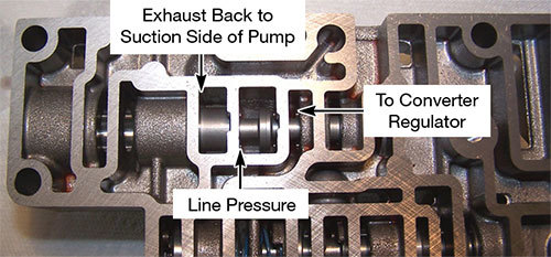
High line pressure can result in harsh shifts, broken parts and even shift timing issues in governor controlled units. Wear between the line pressure and exhaust passages leads to pressure cross-leaking to the exhaust and decreasing overall line pressure. One of the more common examples of wear in this area is the AODE/4R70W (Figure 3).
| Figure 3 |
|---|
 |
Wear within boost assemblies typically results in lower line pressure, as there is diminished hydraulic pressure pushing the pressure regulator valve back from the exhaust position. Low line pressures can result in soft shifts, burnt clutches and also shift timing problems in governor-controlled units. While symptoms from bore wear can occur at all temperatures, they will typically get worse as the transmission warms up and fluid thins out. The symptoms the vehicle exhibits can help to narrow down what valve lineups to check and where to check them.
There are a few different tests that can be done when main pressure regulator valve wear is suspected. Before draining the fluid and dropping the pan, a good place to start is getting a line pressure gauge on the unit, provided there is a line pressure port on the transmission. Problems with overall line pressure can be caused by wear in the pressure regulator valve bore. Once the casting is on the bench, there are a few different approaches to qualifying wear in the bore. Visual inspection is an obvious method, but others, such as the flashlight, wiggle and wet air tests have been used. The least subjective and most repeatable method in determining casting wear is vacuum testing. Measuring the amount of air that can leak between a valve spool and sealing surface in the casting tells us how much fluid can blow by during operation.
Problems with the main pressure regulator valve can have a variety of different symptoms, but with a better understanding of its function, the diagnostic process is quicker and easier. As a circuit begins to lose its ability to hold pressure, the drivability and pressure problems soon follow. Always start with the least invasive diagnostic checks — in this case line pressure — to shed some light on what could be causing a customer’s complaint.
Be sure to check out: Hydraulics Fundamentals Part II: Accumulators & Shift Feel
Zachary Richardson is a Sonnax design engineer. He is a member of the Sonnax TASC Force (Technical Automotive Specialties Committee), a group of recognized industry technical specialists, transmission rebuilders and Sonnax technicians.
Learn More
March 26, 2020
Hydraulics Fundamentals Part VI: Converter Limit Valves
John Varvayanis
April 20, 2020
Hydraulics Fundamentals Part VII: AFL/Solenoid Modulator Valves
May 03, 2019
Hydraulics Fundamentals Part IV: Converter Clutch Control
Bob Warnke
February 26, 2019
Hydraulics Fundamentals Part II: Accumulators & Shift Feel
Maura Stafford
March 26, 2019
Hydraulics Fundamentals Part III: Secondary Regulators
Jim Dial
June 08, 2020
Hydraulics Fundamentals Part VIII: Check Valves
March 03, 2020
Hydraulics Fundamentals Part V: Manual Valves
Jim Dial
December 17, 2020
Hydraulics Fundamentals Part X: Shift & Relay Valves
Jim Dial
Related Units
4R75W Transmission
4R70W Transmission
AODE Transmission
TAAT Transmission
4R70E Transmission
4R75E Transmission
While Sonnax makes every effort to ensure the accuracy of technical articles at time of publication, we assume no liability for inaccuracies or for information which may become outdated or obsolete over time.