July 16, 2021
Resolving Stalling & Overheat Issues After Performance Tuning on RFE Transmissions
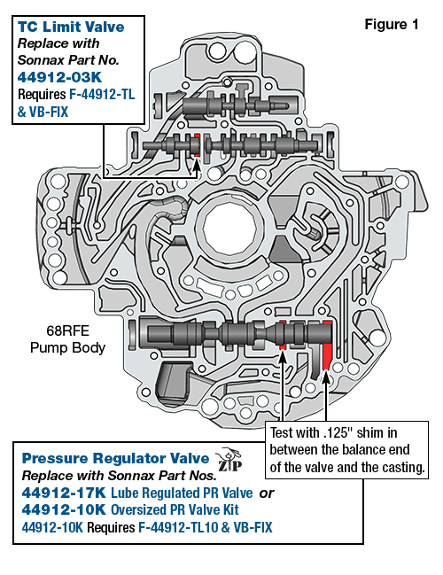
The Chrysler 45RFE, 545RFE, 68RFE family of transmissions has been plagued with complaints of stalling conditions and low cooler flow issues from its inception in 1999. Early on, problems typically pointed in the direction of TC limit valve, as it is in charge of torque converter release pressure, which is the circuit that keeps the torque converter clutch away from the torque converter cover. TC limit valve bore wear was commonly the culprit, especially in early applications. As a matter of fact, the valve was typically so worn that it could be moved easily side to side in the bore (Figure 1). The TC limit valve is still a problem area, and most shops make it an automatic replacement during pump overhaul by reaming the bore and installing Sonnax valve kit 44912-03K.
| Figure 1 – TC Limit Valve & Pressure Regulator Valve Vacuum Test Locations |
|---|
 |
Although time and technology have progressed since the early days of RFEs, these types of complaints have persisted, just in a slightly different form. The pressure regulator valve in this family of transmissions has now surfaced as being the cause not only of this low cooler flow and partial stall condition, but also a fluid overheat complaint. As it turns out, it is the position of the pressure regulator valve that is causing this issue, not necessarily the valve itself.
A majority of customers driving Ram 2500 series, heavy-duty, 6.7L diesel know that an easy and inexpensive way to get better performance and power out of this truck is through an aftermarket performance software upgrade or “tune” as most call it. This upgrade increases horsepower, torque and even provides better fuel mileage. Software for transmission control will also be upgraded so the 68RFE can hold together behind this increase in torque. Although many customers will have this upgrade done, when a truck rolls into a transmission shop for repairs, it may be completely overlooked or not even thought about. A quick and easy way to verify whether you have stock transmission programming is to look at the desired and actual pressure on the scan tool when in the Drive position at a stop.
Stock programming will show between 60 psi and 70 psi in both the desired and actual parameters on the scan tool. Line pressure duty cycle will be between 22% and 24%, then 160 psi at stall.
“Tuned” programming will typically show 100 psi to 105 psi in the desired and actual parameters, with line pressure duty cycle at 5.1%, then over 160 psi at stall. (Note: The desired pressure will still be listed on the scan tool even if the actual is 0 psi, as in the transmission is toast.)
This elevated desired pressure at idle has proven to be the culprit and the cause of the low cooler flow, overheating and torque converter-related complaints, as this low cooler flow issue not only shows up at idle in Drive, it also shows up at any time driving at slower speeds when engine RPM drops back to idle position. Figure 2 shows the dual-stage pump in operation in a high line pressure and high-demand pressure regulator valve position, where both sides of the pump are supplying pump output pressure. This illustration shows three regulating points on the valve based on its position:
1. Regulating point A is the connection to the secondary stage of the pump and exhaust.
2. Regulating point B is regulating the primary side of the pump and exhaust.
3. Regulating point C is the connection from line pressure to the lube and torque converter circuits.
| Figure 2 – Tuned Programming: Pressure Regulator Valve Position at Idle/Low Engine RPM |
|---|
 |
Figure 3 shows the same three regulating positions, but the valve and pump are now in the higher speed and engine RPM position where line pressure can be lower, so only the primary side of the pump is supplying output pressure.
| Figure 3 – Tuned Programming: Pressure Regulator Valve Position at Higher Speed/Engine RPM |
|---|
 |
Figure 2 also shows what position the valve and condition the pump are in during idle in Drive at 700 RPM with line pressure increased via tuning to 105 psi. Note that regulating point C has a very small connection to line pressure. This small connection is a small undercut on the valve spool, which creates low flow to the torque converter circuits (note the green arrow on the valve spool). Typically, this will cause the light to come on when monitoring flow on the Sonnax SonnaFlow, as the GPM will be at .5 or lower. When at idle with desired and actual pressure at 105 psi, and the pressure regulator valve in this position, note that the line pressure duty cycle is at 5.1%. This indicates that the pump is almost at maximum output. To prove this further, line pressure will only jump to 125 psi when the fuse that provides power through the trans control relay is removed. When pressure is at maximum at idle, cooler flow drops further to .3 GPM.
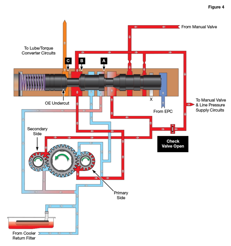
Figure 4 shows the position of the pressure regulator valve with stock programming when desired and actual pressure is between 60 psi to 70 psi and line pressure duty solenoid percent near 22 to 24. Regulating point A is the connection to exhaust, which is connected back to the suction side of the pump. Notice the position of the valve in regulating point C: the connection from line pressure to the lubrication and TCC circuits is much larger, which in this position cooler flow measures 1.3 GPM at idle. That is a significant difference when 1.3 GPM is compared to .5 GPM.
| Figure 4 – Stock Programming: Pressure Regulator Valve Position |
|---|
 |
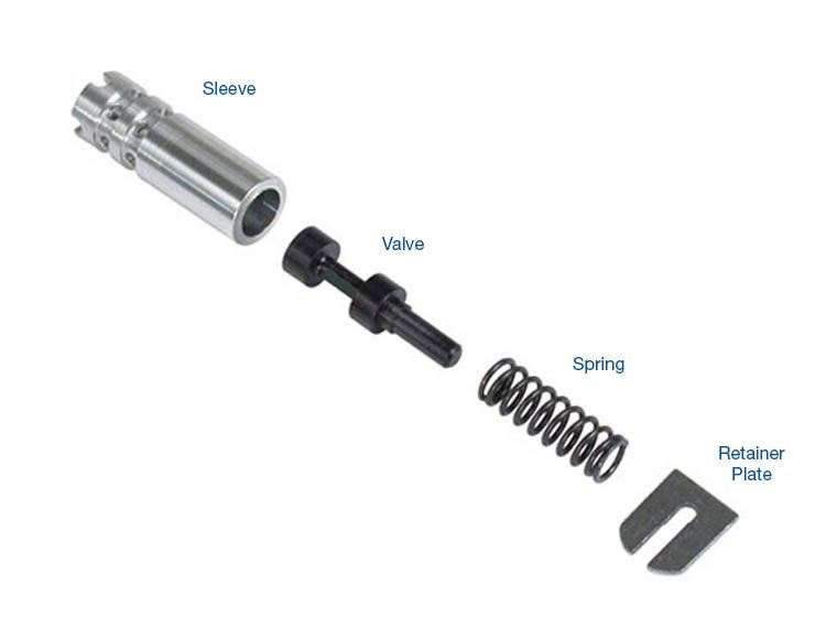
To use the higher line pressure tuning without the side effects of low cooler flow, restricted converter feed and fluid overheat, Sonnax offers a quick and easy drop-in solution: lube regulated pressure regulator valve 44912-17K (Figure 5).
| Figure 5 – Sonnax Lube Regulated Pressure Regulator Valve 44912-17K |
|---|
 |
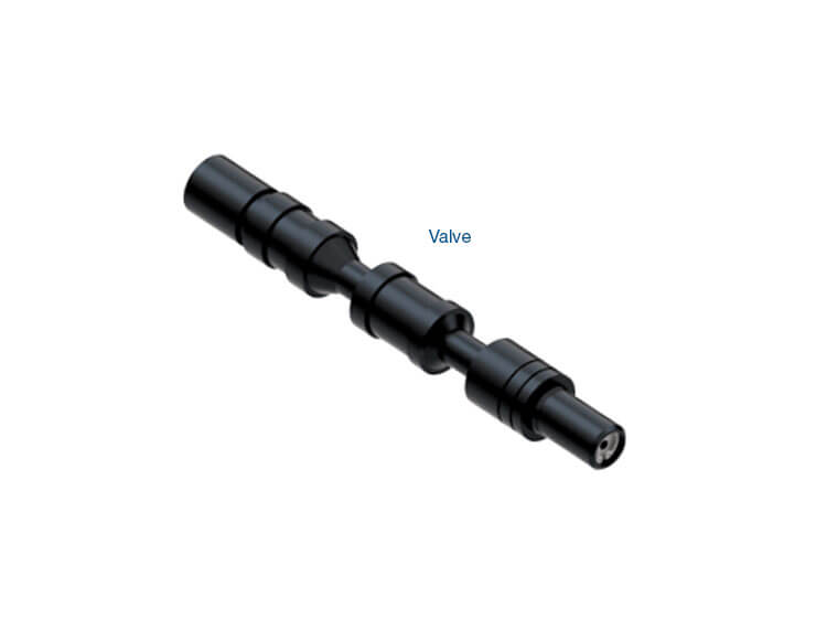
This unique valve has a direct connection from line pressure to lubrication that provides a better connection than the small undercut that is on the OE pressure regulator valve (Figure 6).
| Figure 6 – OE vs. Sonnax Lube Regulated Pressure Regulator Valves |
|---|
 |
The Sonnax valve provides a 60% increase from stock lubrication and cooler flow when at maximum line pressure. It also prevents converter drain back, as the passage that connects the two circuits closes when the vehicle is turned off. Converter drain back has been a complaint in the past as some shops have tried to remedy this low cooler flow issue by drilling line to lube in the pump casting.
Vacuum testing both the TC limit and PR valve bores in the pump is an ideal way to determine if valve or bore wear is the source of a transmission problem. See this Sonnax RFE vacuum test guide for test locations, transmission symptoms and recommended repairs.
Learn More
Related Units
Related Parts
Required
Recommended
While Sonnax makes every effort to ensure the accuracy of technical articles at time of publication, we assume no liability for inaccuracies or for information which may become outdated or obsolete over time.