November 08, 2023
Understanding Lube Flow Control Valves in Toyota/Lexus UA80, UB80 Transmissions
Jim Dial
The Toyota/Lexus UA80 and UB80 transmissions first came out in 2017 in Highlanders and Siennas. The UA80 is used in V6 applications, and the UB80 is paired with 4-cylinder versions. These units are unique in a number of ways and coined as Toyota New Global Architecture type transmissions, also called the “Direct Shift 8AT” 8-speed automatic transmission. This transmission was produced to replace the previous-design U880F 8-speed and the U660/760 units to provide improved performance and efficiency.
There are a couple of things that stand out about this transmission. The first is the fact that the torque converter has moved away from the two-path design to a three-path design. This makes the TCC apply a separate clutch pack and piston inside of the torque converter and can provide better control when in “flex” or partial TCC apply. This new-design torque converter helps eliminate the TCC shudder issue when in partial apply, which the U660/760 transmissions were plagued with.
The second item that makes this transmission unique is that it incorporates a new valve design. This valve is in the cooler return and lube circuits. There were no OE breakdowns of the valve body at the time Sonnax began researching the UA80 and UB80. Based solely on its function, we named it the “lube flow control valve,” or LFC valve for short. The LFC valve is in the middle valve body just below the pressure regulator valve.
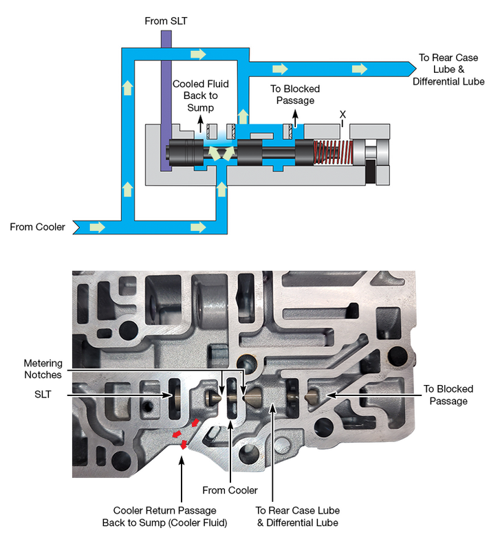
At first look, the metering notches were very interesting, as I have never seen something like that before. The process of reverse engineering the oil circuit uncovered the need for the metering notches and why they were put there. Figure 1 shows a partial circuit diagram of the LFC valve and the circuits connected to it as well as their locations in the valve body casting. Notice the metering notches are there to provide connections to both the rear case and differential lube circuit as well as the circuit that connects cooler return oil to the sump in most positions of the LFC valve. Also notice that the LFC valve is controlled by SLT pressure. The SLT circuit is also connected to the pressure regulator valve. This is a very active circuit, as it is constantly adjusting line pressure to match engine load. A closer look at the LFC valve circuit and the different positions can be found in Figures 2 and 3.
| Figure 1 – LFC Valve OE Partial Circuit Diagram |
|---|
 |
| Figure 2 – Normal-to-Lower Line Pressure LFC Valve Position |
|---|
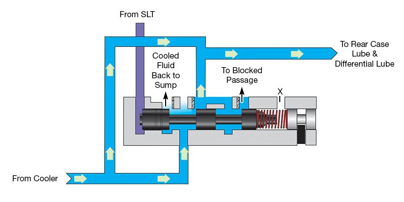 During normal-to-lower line pressure, the LFC valve is positioned more to the left, which directs cooler return oil to the rear case and differential lube circuits. It also makes a connection through the valve's position to the sump, which cools the fluid in the transmission sump. |
Figure 2 shows the LFC valve in a position during normal-to-lower line pressure. The valve is positioned more to the left, which directs cooler return oil to the rear case and differential lube circuits. It also makes a connection through the valve’s position back to the sump, which cools transmission fluid.
During higher loads and higher line pressure, the LFC valve is positioned more to the right by higher SLT pressure. This directs cooler return oil to the rear case and differential lube circuits, but limits the connection from the cooler back to the sump (Figure 3).
| Figure 3 – Medium-to-High Line Pressure LFC Valve Position |
|---|
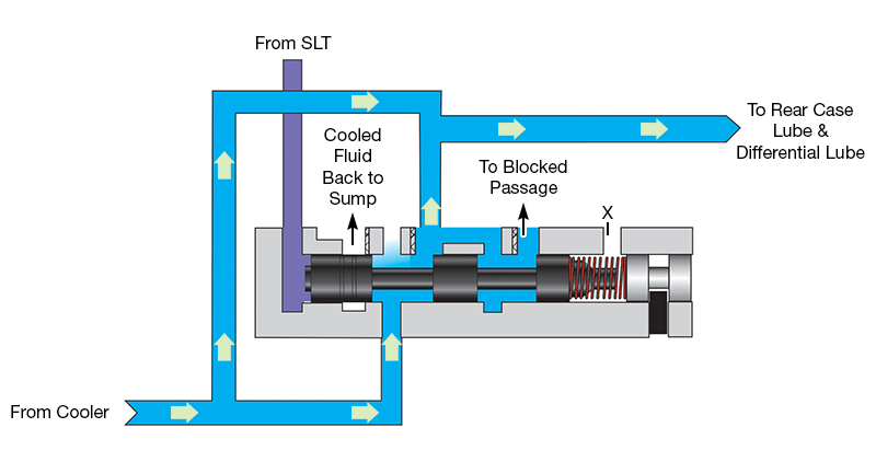 During higher loads and higher line pressure, the LFC valve is positioned more to the right by higher SLT pressure. This directs cooler return oil to the rear case and differential lube circuits, but limits the connection from the cooler back to the sump. This can cause elevated transmission fluid temperatures. Note: It takes less than 20 psi of SLT pressure to start to stroke the LFC valve to the right, and when SLT pressure is high, the LFC valve is moved completely to the right, which can cut off the connection to the sump. |
In summary, this valve prioritizes lube flow to the rear case and differential most of the time and should be checked any time you are rebuilding these transmissions, especially when there is fluid overheat, drivetrain failures or unexplained clutch or brake failures.
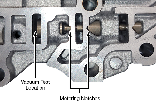
This new-design valve has already shown signs of significant wear. The port where the SLT circuit is fed is the best location to vacuum test the valve (Figure 4). If it fails, replace the OE with Sonnax oversized valve kit 168740-08K to recover hydraulic control and restore cooler/lube performance. The complaints related to a worn bore for this valve would be: transmission fluid overheat, lube failure, planetary damage and even no line pressure rise, as the SLT circuit could be directed to the sump.
| Figure 4 – LFC Valve in Middle Body Casting |
|---|
 |
Jim Dial is a Sonnax technical specialist. He is a member of the Sonnax TASC Force (Technical Automotive Specialties Committee), a group of recognized industry technical specialists, transmission rebuilders and Sonnax Transmission Company technicians.
Learn More
Related Units
U760F Transmission
U660F Transmission
U760E Transmission
U660E Transmission
UA80E Transmission
UA80F Transmission
UB80E Transmission
UB80F Transmission
Related Parts
Required
Recommended
UA80E, UA80F, UB80E, UB80F
Oversized Cooler/Lube Flow Control Valve Kit 168740-08K
-
Helps cure:
- Inadequate lubrication
- Lube failures due to lack of cooler flow
- Overheated fluid
While Sonnax makes every effort to ensure the accuracy of technical articles at time of publication, we assume no liability for inaccuracies or for information which may become outdated or obsolete over time.