Dodge 48RE Hydraulic Features Revealed
Jim Dial
Since the 48RE was introduced in 2003, the valve body hydraulics have been a bit of a mystery. Many have wondered about what makes it different from the 46/47RE, which looks extremely similar. They’re so alike that many have tried to interchange a 46/47RE valve body with a 48RE transmission, which seems to work ok at the start, but after time on the road, the vehicle comes back with a failed torque converter clutch or Overdrive clutch. It’s really frustrating when a 48RE valve body comes into the shop so badly worn in multiple places that it needs to be completely replaced, but all that’s around are 46/47REs. We all know how hard it is to find a salvageable 48RE valve body core.
So, what are the big differences between 48RE and 46/47RE valve bodies? The answer to that is two-fold: there are variations in the pressure curve related to the pressure regulator valve and also in the torque converter clutch solenoid feed circuit.
A little history: the pressure regulator valve on the TorqueFlite family of transmissions is a bit backwards when compared to other pressure regulator lineups. The pressure regulator valve has reduction points that are applied to the various valve spools of the valve forcing the valve in a position to reduce line pressure. When throttle is increased, throttle pressure pushes the throttle pressure plug in the opposite direction, allowing the spring to move the pressure regulator into a position to increase pressure.
Around 1996 when the 46RE was born and higher torque gas and diesel engines were being produced, Dodge added a new valve train near the pressure regulator valve to help increase pressure when in lockup or 4th gear. Figure 1 shows the 46/47RE pressure regulator valve train in 1st through 3rd gear and the four reduction points forcing the pressure regulator valve to decrease line pressure. Figure 2 shows the same lineup, but in 3rd gear with lockup on or in 4th gear. Notice that pressure from the TC apply and or Overdrive apply circuit move the boost valve to the left exhausting reduction point D. This allows the pressure regulator to raise line pressure approximately 10–15 psi when in those ranges to help increase clamping force for the torque converter clutch and Overdrive clutch.
Figure 1: 46/47RE Pressure Regulator Function, 1st – 3rd Gear |
|---|
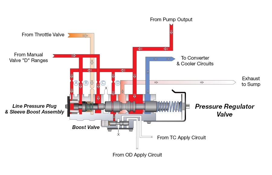 |
| The 46/47RE pressure regulator valve in 1st through 3rd gear with TCC off has four reducing points – A, B, C and D – that oppose the influence of the throttle valve that increases line pressure. This slows down pressure increase as these reducing points are forcing the pressure regulator valve to decrease line pressure. |
| Figure 2: 46/47RE Pressure Regulator Function, 3rd Gear with TCC On or 4th Gear |
|---|
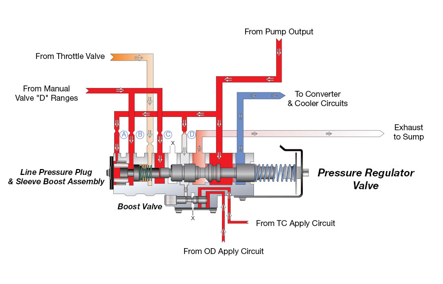 |
| The 46/47RE pressure regulator valve in 3rd gear with TCC on or 4th gear has three reducing points: A, B and C. Reducing point D is exhausted at the boost valve. This allows quicker pressure increase, as TV pressure will be able to position the pressure regulator valve to increase line pressure approximately 10–15 psi. This increase in pressure provides more clamping force for the torque converter clutch and Overdrive clutch. |
The 48RE went into production in 2003, and there were many changes made to the clutch packs and gear train that set this transmission apart from its 46/47RE predecessors. There also were some subtle changes in the valve body to enhance the pressure curve. Figure 3 shows the 48RE pressure regulator valve train in 1st through 3rd gear and the four reduction points forcing the pressure regulator valve to decrease line pressure. Figure 4 shows the same lineup, but in 3rd gear with lockup on or in 4th gear. Notice that pressure from the TC apply and/or Overdrive apply circuit move the boost valve to the left exhausting reduction points A and D. This allows the pressure regulator to increase line pressure approximately 22–28 psi when in those ranges. Since there is no reducing pressure at point A, this also allows the throttle pressure plug to help increase line pressure at a quicker rate.
| Figure 3: 48RE Pressure Regulator Function, 1st – 3rd Gear |
|---|
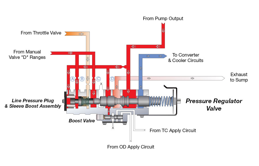 |
| The 48RE pressure regulator valve in 1st - 3rd gear with TCC off has four reducing points – A, B, C and D – that oppose the influence of the throttle valve that increases line pressure. This slows down pressure increase as these reducing points are forcing the pressure regulator valve to decrease line pressure. |
| Figure 4: 48RE Pressure Regulator Function, 3rd Gear with TCC On or 4th Gear |
|---|
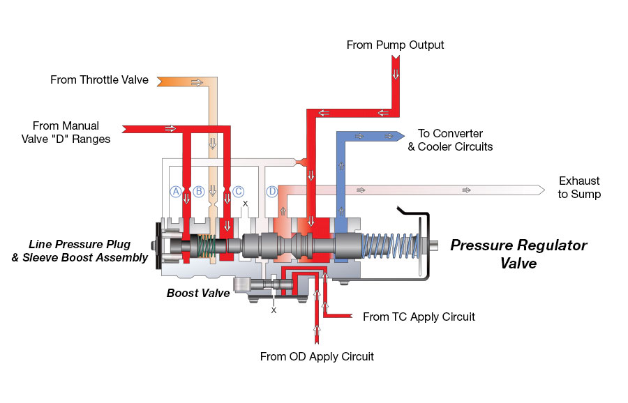 |
| The 48RE pressure regulator valve in 3rd gear with TCC On or 4th gear has two reducing points: B and C. Reducing points A and D are exhausted at the boost valve. This allows quicker pressure increase as TV pressure will be able to position the pressure regulator valve to increase line pressure 22–28 psi. This increase in pressure provides more clamping force for the torque converter clutch and Overdrive clutch. |
These small and subtle changes account for a significant increase in clamping force for the torque converter clutch and the Overdrive clutch, a requirement in these heavy-duty applications, especially when towing.
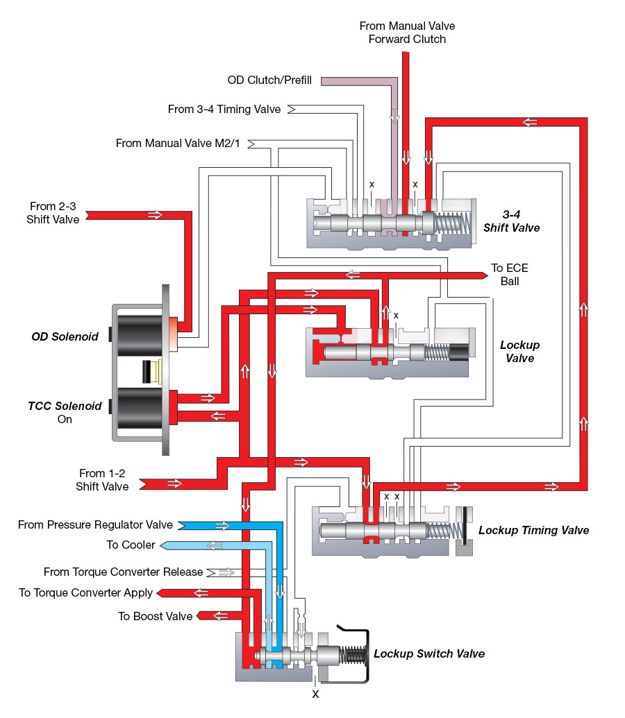
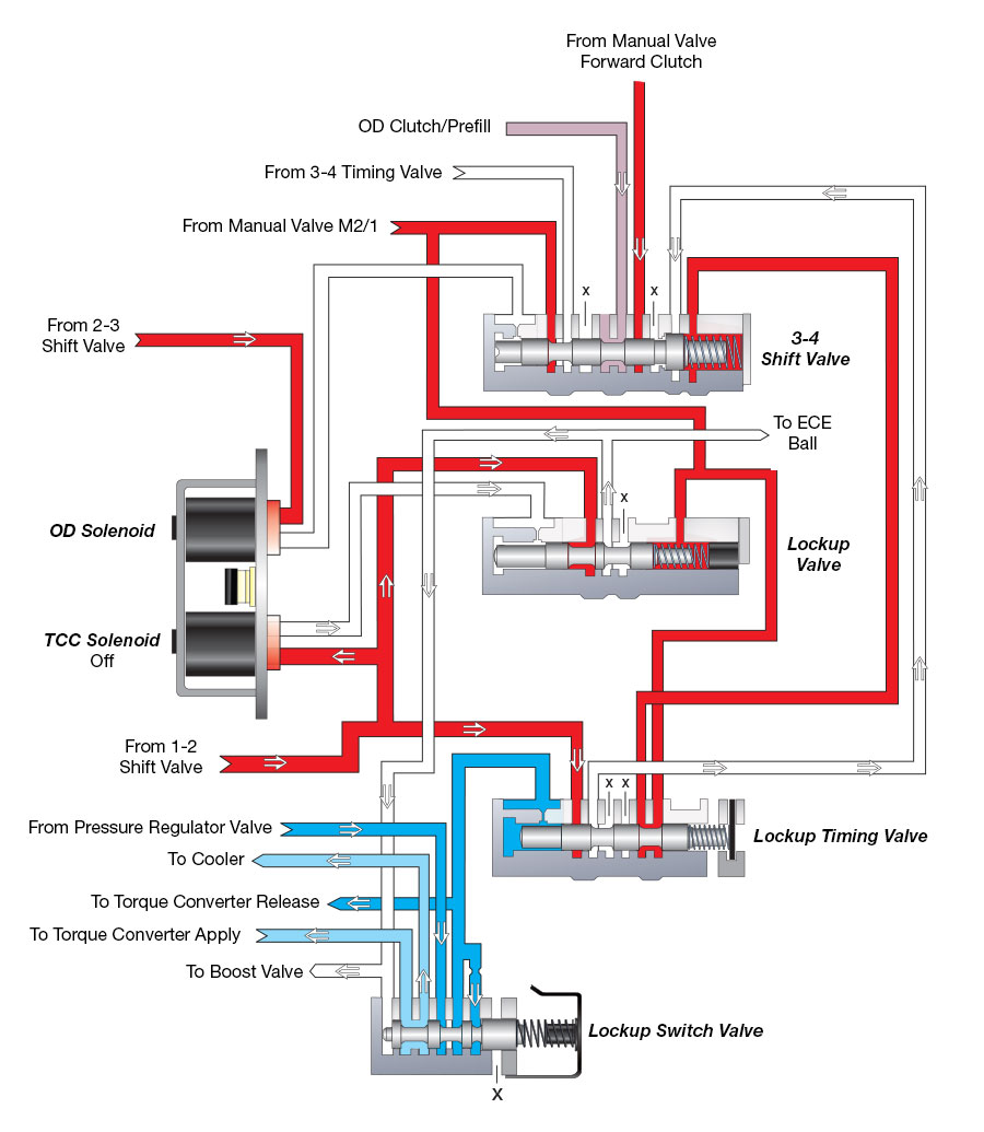
The torque converter solenoid feed circuit and hydraulics for the torque converter clutch control valves on the 46/47RE also are quite different from the 48RE. Figure 5 shows the 46/47RE TCC solenoid feed coming from the 1-2 shift valve and a passage from the manual valve in the manual 2 or manual 1 position connected to the spring side of the lockup valve. Figure 6 shows how this connection cancels lockup from applying.
| Figure 5: 46/47RE, 3rd Gear with TCC On |
|---|
 |
| Figure 6: 46/47RE, Manual 2nd |
|---|
 |
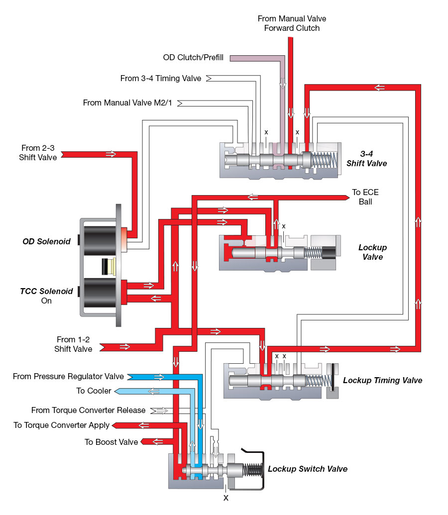
As shown in Figure 7, the 48RE TC solenoid feed comes from the manual valve in any Drive position. This makes it possible to have TCC apply in manual 2nd and even manual 1st. Notice that there is no connection from the manual valve M2/1 circuit to the spring side of the TCC control valve. (Note: manual 1st TCC apply would have to be initiated electronically by an external controller.)
In summary, there were some small and subtle changes made to the 48RE that make a substantial difference in the pressure curve and TCC clamping when compared to a 46/47RE valve body.
| Figure 7: 48RE, 3rd Gear with TCC On |
|---|
 |
Related Units
Related Parts

While Sonnax makes every effort to ensure the accuracy of technical articles at time of publication, we assume no liability for inaccuracies or for information which may become outdated or obsolete over time.