18 Troubleshooting Tips for 4R44E & 5R55E Transmissions
Bob Warnke
It’s time to dust off those cores! With the proper repair, these can be just like money in the bank. You no longer have to sort through cores trying to find “the one that works better than the one that came with the unit ” or, even worse, choose one that looks better in one bore but winds up building a new problem into the unit.
Application and Identification:
The 4R44E was released in 1995 in the 2.3L and 3.0L Ford/Mazda rear-wheel-drive units. In 1996, with the 4.0L, the drive components were beefed up to become the 4R55E. In 1997 the unit became a 5-speed by applying the front servo to obtain an overdriven first and 5th. From that time on, it’s become either a 5R44E or 5R55E. Since 1995 there have been many valve body, plate or solenoid changes.
Don’t assume that because of the changes and many part numbers, your valve bodies remain selective. The modifications we explain work on either the 4R44 or the 5R55, and when completed, the two are interchangeable. Figure 1 identifies the 5R vs. 4R separator plate. After rebuild, the casting can be used for either a 4R or 5R unit.
Complaints:
To start, it’s best to review the “3 Cs” listed for the different valve body repairs for the 4R/5R units. It is important to remember that some complaints cannot be corrected by repairing only one area.
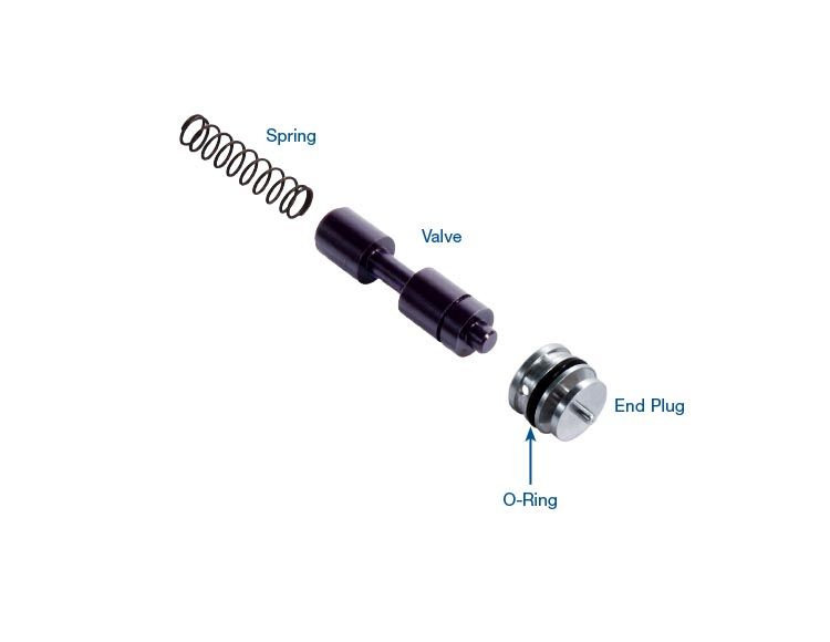
In the TCC system, converter charge oil comes off the pressure regulator valve (37947-05K) and through the TCC modulator valve (37947-07K) whenever the converter is not applied. As the converter clutch applies, the TCC solenoid duty percentage ramps up and the TCC modulator valve strokes. This switches the oil source from the PR valve to the TCC regulator valve (37947-09K). The TCC regulator valve is supplied by line pressure, which is controlled by the EPC circuit.
If line rise is poor because of a dirty EPC solenoid or leakage within that circuit, then feed to the TCC regulator valve will be poor (the solenoid can be replaced with [56842B-01]). The EPC circuit wears and leaks at multiple locations, but it also has an EPC and engagement control valve that sticks (and can be replaced with (37947-11K). This valve acts somewhat like a boost valve. As EPC solenoid output increases, the valve opens to line pressure, further boosting EPC.
From the same circuit the complaint can be delayed reverse, flare 1-2 or 2-3, and harsh shifts following a forced downshift. The harsh shifts occur because the EPC “booster” valve gets stuck at maximum flow. EPC circuit problems also cause broken bands and servo piston seal blowout.
Loss of certain gears can occur due to issues in at least two other circuits. Loss of solenoid oil due to end plug leakage can cause no Reverse, and loss or 3rd or 4th and can be repaired with 37947-13K. Leakage at the coast clutch valve can result in loss of 4th, 5th, or engine braking (you can eliminate leakage with 37947-33K).
 |
The Correct Repair:
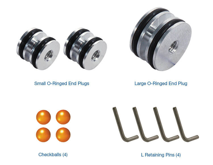
When you examine this valve body (see Figure 2), you see the many “L” retainers. These locate and hold plugs, which separate and seal oil circuits. As the valves toggle, the plugs become loose and allow fluid to pass around them. In the past, some end plugs could be ridged or knurled to reduce oil loss, but in this casting, it’s not possible, due to their depth in the bore and the close fitting tolerances. In newer versions, plugs are anodized and cannot be altered. As these toggle, they wear the casting and not the plug.
Besides the plug and retainer issues, bore wear, as illustrated in the product announcements in this catalog and indicated by the arrows in Figure 4, add to the complaints. With the interdependence of circuits on overall control, it’s not practical to patch-fix this body. For example, delayed engagement is not related to the TCC regulator valve and high TCC slip is not fixed by enlarging a line-to-lube hole. Modifying valve control generally results in shift quality that will not meet customer expectations.
Isolating the Circuits
EPC Line Rise (37947-11K):
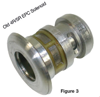
The most effective method to isolate the EPC circuit is to perform an air test with fluid while the body is still bolted to the case. This can be done in the vehicle or at the bench. A quick test adapter can be made from an old 4R/5R EPC solenoid. The coil housing and valve will be removed, and a plug or epoxy used to seal the inboard circuit (see Figure 3).
Supply 50-70 psi of air into the adapter. No leaks should be visible at the locations shown in Figure 4. Any leakage is reduction of EPC pressure and line rise while in operation. Remember, though, as operating temperature increases, valve clearance and the flow rate (viscosity) of ATF increase. You can duplicate hot fluid at the bench by filling the case and valve body with solvent, then bolt up and test with the adapter.
TCC Modulator Valve (37947-07K):
A TCC modulator valve that will not stroke or may have partial stroke can be diagnosed on a road test. The SonnaFlow® must be installed and converter fluid must reach 150 degrees Fahrenheit before the thermal element opens, allowing for external cooler flow. Flow will increase from an average of 1.4 GPM with TCC off, to 2.3 GPM-plus under full apply. The scanner should be used during this drive to monitor TCC duty cycle percentage. As modulation increases to 50%, the solenoid should have fully stroked the TCC modulator valve. When you see the sharp rise in GPM on the SonnaFlow®, the valve has fully stroked. If cooler flow does not rise as TCC apply is commanded or the engine stalls upon forward engagement, inspect the TCC solenoid first. If the engine stalls forward and reverse, look for blown gaskets, a worn pressure regulator bore (which you can replace with 37947-05K) and then pump or converter issues.
TCC Regulator Valve (37947-09K):
Excess TCC slip or code 628 or 741 is often caused by low apply pressure. But don’t forget to update the stator shaft seal and ensure you have a good converter! The TCC regulator valve is designed to limit apply pressure to protect the converter piston. 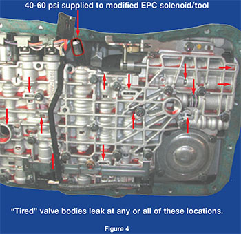 The bore for this valve wears and apply pressure is reduced, so the TCC percentage you saw on the scanner can no longer control the slip RPM.
The bore for this valve wears and apply pressure is reduced, so the TCC percentage you saw on the scanner can no longer control the slip RPM.On a road test, TCC slip is available with a scanner, seen as TCCMACT RPM. This is calculated or actual engine RPM to turbine RPM difference. When you see a TCC percentage of 70% or higher and high slip of TCCMACT RPM 140 or more, your apply circuit has insufficient clamping force. But is it due to converter, seal or insufficient apply pressure?
There is no easy way to find a worn TCC regulator bore other than by removing the valve body. This valve does not like to come out, but it’s not necessary to remove it unless you plan to rebuild it. We supply the disassembly procedure. This valve can be Wet Air Tested as shown in Figure 6. Fluid leakage below the nozzle, back toward the solenoid, indicates a leak in the TCC regulator valve circuit.
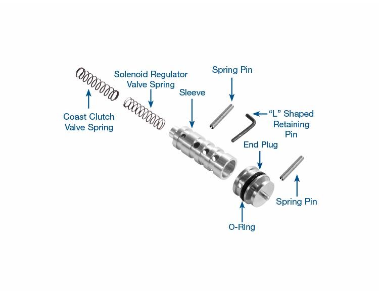
CCS Valve (37947-33K):
The coast clutch shift valve lives in the same bore as the TCC regulator. The CCS is not modulated, but controlled as an on-and-off valve by the SSD/CCS solenoid. When this bore is worn, the solenoid oil flows around it, resulting in the loss of overdrive servo release pressure. This results in no 4th in a 4R or no 2nd and 5th in the 5R unit. If it sticks, the coast clutch will not apply. This wear can be found on a hydraulic test bench or with the Wet Air Test in Figure 6. Fluid coming out of the channel indicated by the pen tip indicates leakage in the Coast Clutch valve circuit.
What to Expect:
Valve bore wear may occur at low service use, depending on driving conditions. The two modulated circuits of TCC and EPC should always be inspected due to their valve activity. Now, the question: Install a specific repair or perform a complete rebuild? That decision is ultimately yours, as you forecast how long a marginal bore may last. A repair for longevity requires tooling. The process creates contamination, so it’s best to strip the entire casting. We supply various tips that, with practice, will help you to dismantle one in less than 20 minutes.
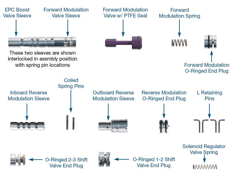
The first time you rebuild a complete valve body can be comparable to overhauling an unfamiliar transmission. Similar to a transmission, it’s most effective when you can do more than one at a time. It’s best to save cores and build several valve bodies at one time, improving efficiency and profits! The reaming process is not difficult and the sleeves install easily. The sleeves will now contain the oil circuit without end plugs, so there are few areas to leak or parts to move.
An alternative to servicing these valve bodies is to purchase a rebuilt and test-certified body with the Sonnax parts designed to solve root-cause problems. The sleeves shown in this material are visible after installation, providing visible assurance that the circuits have been addressed.
 |
Is this tech helpful? Provide us with your feedback at the end of the article.
Troubleshooting Tips:
These tips are not about common problems such as blown gaskets or dirty valve bodies. These only include valve body problems not visible during a rebuild.
No/Slow Reverse:
The SSA solenoid must be turned on, allowing flow through the solenoid, or direct clutch will not apply until EPC rises to 20 psi. The direct clutch psi will then slowly rise following EPC until clutch holds. Always install new servo pistons. Both servos are charged on the release side in reverse. Inspect the center support sleeve, sealing rings and direct drum sleeve for cracks. Ensure the vehicle has line rise, as reverse will not engage until line is 120 psi.
Delayed Reverse and Forward:
The separator plate must be aligned with pins. If not, the bolt threads will separate the case from the plate, causing a line pressure leak.
Servo Covers Blown out of Case:
Inspect for causes of high line psi such as pressure regulator bore or boost sleeve wear, or line booster valve stuck inboard.
Servo Rubber Separated/Blown Off:
This often occurs from pre-assembly damages, so inspect carefully before installing. The rubber lip separation occurs from heat and high pressure. Both servos are pushed toward the cover in reverse, so check for cause of high line pressure.
No 2nd, 1-2 Slide or Soft 2nd Gear Starts:
Air test the rectangular circuit, 5 openings in from EPC solenoid. No cross leakage should be visible! Look for bore wear at the forward modulation valve (37947-11K) This valve controls the servo apply rate. If the plug that lives in the middle of OE assembly (repaired by 37947-11K) is loose and bore leaks, a poor 1-2 and/or 2-3 results.
No 2nd or 4th, Erratic Direct Clutch, No Upshift:
The solenoid regulator valve is likely out of position. With SSB solenoid removed, the end of the casting to edge of the long aluminum plug will measure 1.720” when L pin is installed properly.
No Coast Clutch Pressure:
Inspect the bore plug for wear at the TCC regulator valve. Sonnax 37947–09K kit eliminates the leak and bore plug here. The bore for the coast clutch shift valve wears out. Insert the valve: no side-to-side movement should be visible.
No Overdrive Servo Apply psi:
The coast clutch shift valve may be out of position, the bore worn severely or the dumbbell-shaped valve (opposite bore from the TCC modulator) is not being retained correctly. This L pin falls out of position easily. Timing valve may be stuck toward the end plug or the spring is not on center, which causes it to coil bind. Kick-down valve may be stuck or spring missing.
No OD Servo Release (No Overdriven 2nd in 5R & No 4th in 4R):
Mismatched separator plate at 5R/4R identification (see Figure 1).
OD Band Failure, No Overdrive Release psi:
The 3-4 shift valve may not be positioned due to a loose SSC solenoid. Bracket must hold it in flush.
Broken Bands, No EPC Blow-off, EPC psi Too High:
Relief Tee near the pressure regulator is not opening or mismatched plate without a hole here and no relief used at forward modulator end plug. The EPC spring bore is often tapered, which alters spring operation. The combined 37947–11K regulation kit addresses this problem.
Low EPC, Soft Shifts, Slip in 3rd:
Multiple EPC leakage points. Use the 37947–11K kit, which address this entire circuit. Good maximum EPC is 125-130 psi in OD and maximum of 144 in reverse. EPC should not drop more that 15 psi during TCC apply.
Low EPC Pressure and No Lockup Control:
If TCC modulator valve sticks, EPC will only obtain about 65 psi.
Flare on 2-3 Shift, 4R( 3-4 on 5 Speed):
The servo pin bore is worn on the intermediate servo or the spring on the piston is too strong.
No 3rd or 4th:
The 2-3 shift valve spring is missing or installed wrong. Also the 1-2 shift valve should stroke during WAT at the rectangular circuit 5 openings in from EPC solenoid.
TCC Applied Prematurely, Harsh Shifts:
If the solenoid is restricted or grounded, the TCC valve can stroke and apply the converter clutch.
Poor Converter Charge, Delayed Engagements:
The balance spool or innermost bore for the pressure regulator is worn out.
Shift Solenoids:
Very rare to have a shift solenoid problem on these units. It’s more common to have a loss of solenoid oil psi due to loose end plugs.
Bob Warnke is vice president of technical development and a member of the TASC Force® (Technical Automotive Specialties Committee), a group of recognized industry technical specialists, transmission rebuilders and Sonnax Industries Inc. technicians.
Related Units
Related Parts
Required
Recommended
4R44E, 4R55E, 5R44E, 5R55E
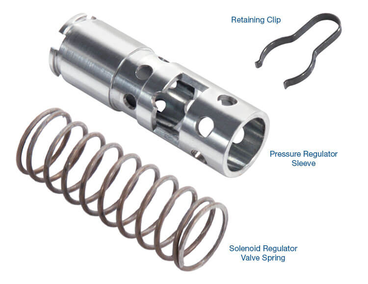
Pressure Regulator Sleeve Kit 37947-05K
-
Helps cure:
- Delayed engagement
- Poor shift quality
- Low line pressure
- High line pressure
- Overheating
- Low cooler flow at idle
Required
Recommended
4R44E, 4R55E, 5R44E, 5R55E
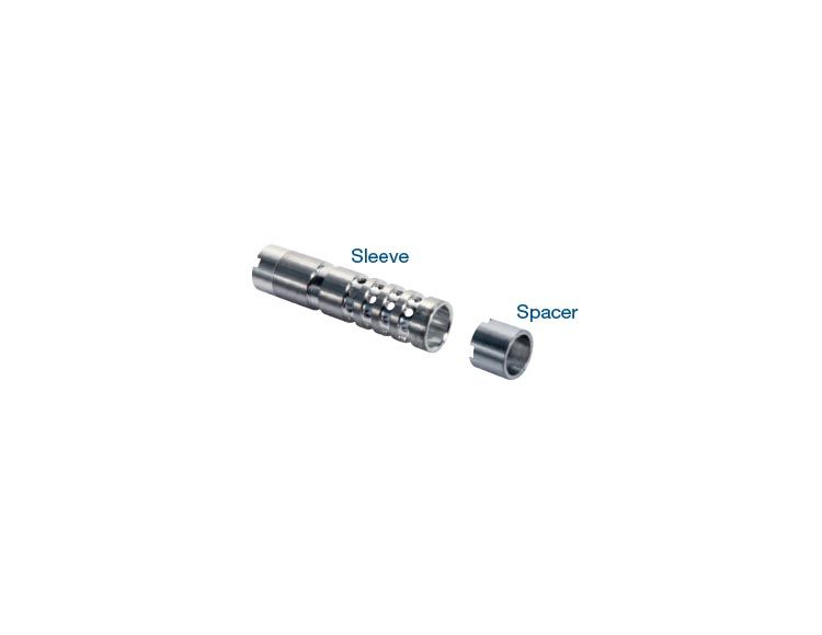
TCC Modulator Sleeve Kit 37947-07K
-
Helps cure:
- Code 1741
- No lockup
- Engine stall on FWD engagement
- Poor converter fill & delayed engagements
- Low cooler flow
Required
Recommended
4R44E, 4R55E, 5R44E, 5R55E
TCC Regulator Sleeve Kit 37947-09K
-
Helps cure:
- Code 628, 1741
- TCC apply concerns
- TCC cycling
- TCC surge
- High TCC slip RPM
- Overheated fluid
- Overheated converter
Required
Recommended
4R44E, 4R55E, 5R44E, 5R55E
EPC & Engagement Control Kit 37947-11K
-
Helps cure:
- 2nd Gear starts
- Flare on 1-2 or 2-3 shift on 4R, or 2-3, 3-4 on a 5R
- No Reverse
- Poor shift quality
- Delayed Forward
- TCC slip
- Code P0741
Required
Recommended
4R44E, 4R55E, 5R44E, 5R55E
Oversized Coast Clutch Valve Kit 37947-33K
-
Helps cure:
- No engine braking in D3 to low
- No 4th (4R44E/55E)
- No 2nd (5R44E/55E)
- No 5th (5R44E/55E)
- No coast clutch apply
While Sonnax makes every effort to ensure the accuracy of technical articles at time of publication, we assume no liability for inaccuracies or for information which may become outdated or obsolete over time.