January 05, 2015
Vacuum Testing for Leakage
This article has also been translated into Russian and Spanish:
Читать эту статью нарусском
Lea este artículo en español
Why Vacuum Test?
A properly diagnosed transmission means no wasted time and money on repairs which aren’t needed or aren’t working. Sonnax pioneered the use of vacuum testing valve bodies by recognizing that a worn valve or valve body bore can result in incorrect hydraulic pressures, leading to poor performance or failure of the transmission.
The same tools and techniques used for years in Sonnax engineering and tech labs are also available to shops seeking a fast, easy and reliable method of evaluating bore wear and the effectiveness of repairs. Sonnax offers a quality vacuum test stand kit and a growing collection of testing guides for various units to help rebuilders get started.
 |  |
There are many methods to check for and evaluate the severity of worn valves and bores – valve body testers, visual inspection, wet air testing, measurement tools, wiggle/sag (deflection) tests, etc. – but vacuum testing offers many advantages over other inspection techniques:
 Economical - A vacuum test stand has a relatively low initial cost and requires minimal maintenance.
- Quick & Easy - Vacuum testing is easy to learn. It doesn't take long to become skilled at rapidly testing multiple areas.
- Quantitative - Vacuum testing returns a specific value (inches of mercury) which, with experience, allows rebuilders to establish pass/fail standards for proper valve body function.
- Reliable - Test results are accurate and repeatable when routine calibration and basic test procedures are performed.
How Does It Work?

Vacuum testing essentially involves isolating or sealing a circuit containing one or two valve spools and attempting to pull air between the valve spool(s) and the bore. As airflow is restricted by tight clearances, we are able to create, hold and measure vacuum. Since we are rating a vacuum, the measurement will be in inches of mercury, or negative pressure.
To maintain a hydraulic seal, there is very little design clearance between the critical valve spool and mating bore. As wear occurs, this clearance increases. A perfect vacuum (no leakage points) will measure 29.9" of mercury, although that does change with elevation. Clearance always exists, so no circuit will pull a perfect vacuum. As wear occurs and leakage increases, vacuum reading levels will decrease. In checking valve clearance, the vacuum loss is directly proportional to the amount of wear.
Figure 4 shows a cross-sectional view of a TF-81SC main pressure regulator valve bore in which the balance line circuit is being vacuum tested. The vacuum test plate or nozzle seals the balance line port and tries to pull air from the neighboring exhaust port through the clearance between the valve spool and bore. An extremely good circuit reading might approach 22" or 23" of mercury. A severely worn bore could have a reading as low as 8" of mercury.
Where Should I Test?

Sonnax vacuum test guides are a great tool to use in evaluating the valve body or pump body to identify areas most prone to wear, the complaints often associated with wear in these areas, and the location to test circuits in a specific unit. A growing collection of guides to vacuum test locations can be viewed and downloaded anytime.
Here are some basic guidelines for vacuum testing which may come in handy, especially if you want to develop your own vacuum test location guides:
Targeted Testing
If you have a specific complaint and there are valves you know are directly related to certain codes or drivability complaints, you may choose to start there. For example, a 4L60-E with an 1870 code should have the TCC regulator valve bore vacuum checked for leakage.
General Testing
If you do not know where to start, or if you want to evaluate the valve body or pump body more completely, begin by checking different circuits based on their level of valve activity:
- Active valves - The valves doing the most cycling in the bore are most likely to wear first. Boost valves should always be checked because EPC or throttle pressure changes keep these valves constantly moving in their sleeves.
- Modulated valves – Valves reacted on by low-resistance, modulated solenoids tend to wear quickly. These valves oscillate in the bore in a relatively narrow, somewhat-consistent location and are actuated by 32 Hertz solenoids. This is fast enough to modulate the valve, but slow enough to oscillate or stroke the valve in the bore before changing direction. The new design, faster 300 Hertz solenoids still modulate or position the valve, but much less etching of the bore occurs because they pulse faster than the valve can stroke any significant distance. Examples of low-resistance modulated valves to check would be AODE and 4T60-E converter valves.
- Regulating valves - These valves are controlling pressures to a set parameter, and wear will make the pressure out-of-spec and possibly set a code. Regulating valves also typically operate in a relatively narrow section of the bore, creating wear at the very location where sealing is the most critical. Examples would be main pressure regulators, secondary regulator valves and solenoid regulator valves.
The circuit or port being tested must be captive or sealable. Balance ports are great locations to perform vacuum tests for this reason. Dense foam or rubber padding can be used to help seal off circuits which are open to the opposite side of the casting. Sonnax wet air test plates make great tools for sealing off circuits for testing. When sealing a circuit/port for testing, make sure you do not seal off the neighboring port that would supply the air source needed for leak detection, because a false high vacuum reading can result.

When using a test plate, we recommend that you apply a small amount of assembly lube around the worm tracks of the circuit/port being tested. This provides a much better seal with the test plate, particularly if there are any knicks on the valve body surface. Checking some locations might require getting creative with test plates. Adapters can be made by drilling through a small rubber ball, disassembling solenoids and using the snout end with O-rings, or by cutting a sheet of Plexiglas to size and using push connect fittings.
Valves which tend to operate in a narrow, somewhat-consistent location develop wear and are more accurately tested in their operating position. Small check balls, washers or retainers can be used to position a valve into operating position prior to vacuum testing.
Keeping an oil circuit handy will help lead you to the key ports for vacuum testing. For units you frequently see in your shop, consider developing your own vacuum test guides similar to the one shown in Figure 6. Show the entire valve body along with the valve locations and ports which should be vacuum tested. Complaints associated with a low vacuum reading at designated ports also can be added as a quick and easy method for evaluating a valve body.
 |

Proper Equipment and Calibration is Essential for Accurate Vacuum Testing!
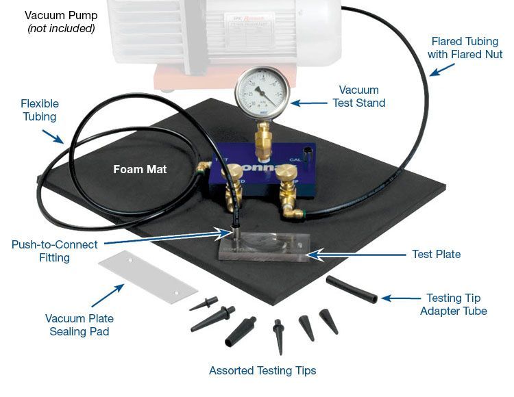
The Sonnax vacuum test stand kit (Figure 7) is a great alternative to building your own testing rig. It comes with an assortment of testing tips, high-quality brass needle valves and test orifices for easy calibration plus easy-to-follow instructions for assembly, calibration and use. A vacuum pump is not included in this kit. Sonnax recommends a 3cfm pump when vacuum testing valve bodies.
What Should My Test Results Be?
While a properly calibrated and maintained test stand will give consistent vacuum reading results for a specific circuit and amount of wear, evaluating those results requires that you establish your own pass/fail criteria. Pass/Fail recommendations for many Sonnax transmission parts can be found on individual product pages and within part instructions. The pump, gauge and any calibration orifices used in specific equipment configurations will greatly influence vacuum readings. Other parameters which influence vacuum readings are the number of spools tested in a captive circuit, spool diameter size and contact length of the spool within the bore.
Test results will vary depending upon how you set up your particular vacuum stand, the maximum vacuum capacity of your pump and, in some cases, the altitude where you are located. Pass/Fail standards are specific to your setup and process, but they also must be based on your experience, quality sensitivity, warranty concerns and cost/pricing structure. We recommend that you keep a record of vacuum results for each valve body at each tested circuit/port location. This lets you compare results over time to help determine for your own shop what an acceptable vacuum reading is for each location.
Learn More
March 18, 2021
Transmission Testing & Repairs: It’s NOT Business as Usual, so Make Sure You’re Vacuum Testing
Randall Schroeder
November 03, 2022
Watch Out for 4R70W Pressure Regulator Valve & Casting Wear
Brian Wing
September 16, 2024
Building a Basic Vacuum Testing Tool Kit
Randall Schroeder
Related Parts
Required
Recommended
Vacuum Test Stand Kit VACTEST-01K
-
Helps cure:
- The need for a quick, easy & repeatable method to test valve & bore wear
While Sonnax makes every effort to ensure the accuracy of technical articles at time of publication, we assume no liability for inaccuracies or for information which may become outdated or obsolete over time.