GM TCC Circuits
Maura Stafford
Oh no! Not another sequel! Haven’t you heard that expression: if you’ve seen one, you’ve seen ’em all? That can be true for movies (think of the “Rocky” series), reality shows (Survivor, The Bachelor, The Apprentice) and even transmissions.
Transmissions? That’s right. Take, for example, the GM converter clutch circuits. The overall plot has stayed the same: apply and release the clutch. Only the cast of characters (valves and solenoids) and individual story lines (On/Off vs. PWM, limiting apply and/or release pressures, etc.) has changed. So once the basic TCC (torque converter clutch) circuit is understood, the more complex circuits can be deciphered easily.
While there can be any number of ways to categorize GM converter clutch circuits, one basic way is by the solenoid control method. There are three basic circuit styles:
- 1 solenoid – 1 TCC Enable (On/Off)
- 2 solenoids – 1 TCC Enable & 1 PWM (Pulse Width Modulated)
- 1 solenoid – 1 TCC PWM Generally, this category list also indicates the design progression and control complexity.
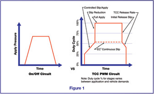
So, why the circuit sequels? Was anything gained or lost with each subsequent style? Compare the early TH200C TCC circuit that used a TCC enable solenoid activated by a governor switch to one of today’s modern transmissions with a computer that analyzes a multitude of inputs (engine temperature, transmission temperature, brake switch, pressure switch, vehicle speed sensor, throttle position sensor, crankshaft position sensor, etc.) in order to duty cycle the TCC PWM solenoid. By monitoring the various operating parameters, the computer is better able to determine the best time for applying or releasing the converter clutch, but also at what rate and firmness the clutch should apply or release. (A line graph depicting the TCC apply and release of both these type circuits is shown in Figure 1).
The sophistication of the circuits has not only led to improved drivability, but more efficient power flow and increased fuel economy. By using a PWM-style circuit, a smoother apply and release occurs and the TCC is permitted to come on sooner without being objectionable. Consumer demand for better comfort and more infrequent and cheaper stops at the gas station are making these circuit improvements a necessity.
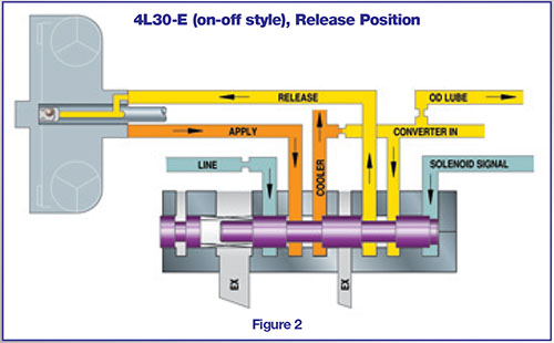
The on-off style 4L30-E provides a good example of a very basic TCC enable solenoid circuit. Only one on/off solenoid and one valve directly control the apply and release of the TCC. The converter clutch control valve, biased by solenoid signal fluid pressure and opposing spring force, routes fluid pressure into the apply or release circuits (see Figure 2). This either fully engages or releases the converter clutch. The drivability “feel” is controlled by metering the apply flow with the orifice in the line circuit, and release flow with the checkball in the turbine shaft. This allows the converter pressure and flow to vary with line pressure. Some 2000-up models changed to a TCC PWM solenoid and 3 TCC valve-style circuit similar to the 5L40-E, which will be discussed later.
A more complex version of a single TCC enable solenoid system is the TH440/4T60 (see Figure 3). This circuit has a converter clutch apply valve that functions much like the 4L30-E, in that it routes converter feed fluid pressure either to the apply or release side of the converter clutch. However, this valve has multiple spool diameter sizes and uses line pressure to assist spring 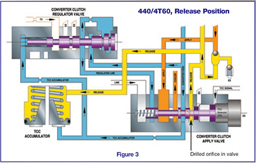 force in biasing the TCC signal pressure from the solenoid. This aids in the prevention of valve hunting, which could create lockup complaints and/or burned converters. Additionally, this circuit uses a converter clutch regulator valve to regulate converter feed pressure into apply pressure prior to it being routed through the apply valve and into the converter. Balanced regulated apply pressure is opposed by spring force and TCC accumulator and TV pressures to control this regulator valve. While this system still either fully engages or releases the converter clutch, it allows the converter apply pressure to vary with torque demand, and the clutch to be applied more smoothly for improved engagement feel. Another feature incorporated into this circuit is a TCC blow-off valve, which controls the converter fill circuits to a maximum pressure of 130 psi.
force in biasing the TCC signal pressure from the solenoid. This aids in the prevention of valve hunting, which could create lockup complaints and/or burned converters. Additionally, this circuit uses a converter clutch regulator valve to regulate converter feed pressure into apply pressure prior to it being routed through the apply valve and into the converter. Balanced regulated apply pressure is opposed by spring force and TCC accumulator and TV pressures to control this regulator valve. While this system still either fully engages or releases the converter clutch, it allows the converter apply pressure to vary with torque demand, and the clutch to be applied more smoothly for improved engagement feel. Another feature incorporated into this circuit is a TCC blow-off valve, which controls the converter fill circuits to a maximum pressure of 130 psi.In 1991 General Motors released the 4T60-E, which contained its first dual solenoid system utilizing PWM for the converter circuit (although some early units were still single solenoid, non-PWM). The design of this circuit is very similar to the TH440/4T60, only refined in the area of clutch apply and release for an even smoother and more controlled engagement feel (see Figure 4). The circuit still contains the same style converter clutch apply valve, which functions in the same manner to direct flow to the apply or release side of the converter clutch.
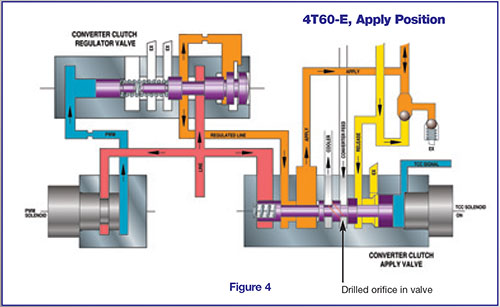
However, the converter clutch regulator valve is now two pieces, regulates line pressure instead of converter feed into apply pressure, and is controlled by a PWM solenoid. The PWM solenoid is controlled by the computer, and varies the duty cycle (on/off time) from 0% to 100%, thereby adjusting PWM pressure which positions the converter clutch regulator valve (instead of TV pressure in the TH440/4T60). This allows the apply pressure to be more finely controlled based on multiple transmission inputs, and permits the converter clutch to be “slipped” on or off, depending upon driving needs. The addition of the PWM solenoid eliminated the need for a TCC accumulator. The transition from the 700-R4/4L60 on-off-style converter circuit to the 4L60-E enable and PWM solenoid controlled circuit is very similar to that of the 4T60-E.
While PWM circuits allow the TCC to be slipped on and off and fully applied, it should be noted that some applications offer an EC3 (electronically controlled capacity clutch) PWM system. The hydraulic circuitry between the PWM and EC3 systems is the same, but the computer programming varies. An EC3 unit allows for a continuous low rpm converter clutch slip, which still improves fuel economy while further enhancing drivability by reducing driveline torsional disturbances.
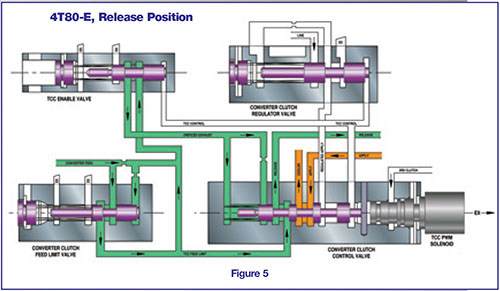
The next major progression in the GM converter circuits was to eliminate the enable solenoid and use only one TCC PWM solenoid to control the apply, regulator, and often additional valves. A good example of this is the 4T80-E (see Figure 5), which is virtually identical hydraulically to the more common 4L80-E. The duty cycled TCC PWM solenoid pulses 3rd clutch oil into TCC control fluid pressure, which controls three valves: TCC enable, converter clutch control (apply), and converter clutch regulator. In the release position, the TCC enable valve directs feed limit pressure to the spring side of the apply valve. This prevents the apply valve from hunting between apply and release due to the pulsed pressure control.
As the computer starts increasing the duty cycle, the enable valve is the first to stroke, allowing the feed limit pressure to exhaust from the spring side of the apply valve. The apply valve is then stroked, redirecting release pressure from the converter to the enable valve for an orificed exhaust. Pulsed TCC control pressure then adjusts the regulator valve according to duty cycle, which regulates line into apply pressure that is routed to the converter for a controlled slip engagement. The converter feed limit valve prevents release pressure from exceeding 125 psi (93-107 psi on the 4L80-E). One potential hazard in this system is that if the apply valve becomes stuck in the “on” position, there will be no release pressure to the converter and overheating will occur.
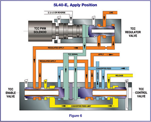
The 5L40-E (see Figure 6) also uses a single TCC PWM solenoid to control the valves, and has eliminated this hazard through different hydraulic porting. Pulsed TCC signal pressure strokes the TCC control valve and enable valve simultaneously. However, should the control valve become stuck in the apply position, the converter feed limit circuit will ensure the converter still has flow. In this design, the converter feed limit valve was also eliminated.
Each of these circuits is slightly different, but the progression has shown the increased emphasis on efficiency and drivability. Which is the best? They all have advantages and disadvantages, but were designed to best suit the transmission with the technology at the time. Sonnax offers numerous parts to replace and improve components in a number of these circuits (see Figure 7). Someplace there’s a room full of screenwriters working on Rocky VI or the next Survivor series, and as long as there’s money to be saved, a new approach to try, or an improved design, you can guarantee another sequel to the GM converter clutch circuit.

Maura Stafford is a Sonnax project engineer and a member of the Sonnax TASC Force® (Technical Automotive Specialties Committee), a group of recognized industry technical specialists, transmission rebuilders and Sonnax Industries, Inc. technicians.
Related Units
4T60 Transmission
4L30-E Transmission
5L40-E Transmission
4T80-E Transmission
4T60-E Transmission
4L60 Transmission
4L60-E Transmission
4L80-E Transmission
While Sonnax makes every effort to ensure the accuracy of technical articles at time of publication, we assume no liability for inaccuracies or for information which may become outdated or obsolete over time.