CalibRATIOn
Maura Stafford

It doesn’t take many flips through any of the Sonnax Transmission Specialties® catalogs to notice that we offer many valve assemblies with various ratios. What is a ratio, why do we have so many, and is it important to consider during a rebuild?
For the purposes of this discussion, “ratio” can be defined as the relationship in size between two or more similar parts. For a typical boost valve available in different diameters, it is the ratio between the boost valve reaction area and the reaction area on the regulating valve. Anybody familiar with rebuilding Toyota valve bodies has discovered that most applications have enough different-sized boost valve assemblies to make your head spin. The parts look the same initially, but the valve spools measure differently in size for different vehicles. Not that this is an Asian phenomenon – all the OEMs have designed units in this manner.
The two primary reasons why the OEMs do this is to save money and increase flexibility. A particular transmission (03-72LE, 4L60-E, etc.) can be used in various vehicle models, each having different needs in regard to torque capacity, horsepower, shift feel, and other factors. For example, a 4L60-E transmission was used in an Isuzu Hombre (1999) with a 2.2L, 4-cylinder engine having 120 horsepower (HP) and 140 ft-lbs of torque. The same unit was also used in a 5.7L, V8 Pontiac GTO requiring 350 HP and 365 ft-lbs of torque. With such widely varying torque ratings, the transmission requires different clutch and/or band holding capacities, which in turn require different main line pressures.
One simple and inexpensive method for achieving different line pressure curves is to vary the main pressure regulator boost valve spool ratios. The typical boost assembly is used to increase line pressure by providing an additional force, influenced by throttle and reverse gear pressure, so that when high torque conditions are required, line pressure is raised. By altering the size of the boost valve spool diameters, the manufacturer can use hydraulic pressure on the various valve spool areas (force = pressure x area) to tailor the line pressure curve to a specific application. In most instances, these valve spool size changes can be accomplished without changing the outside diameter of the boost sleeves, thus allowing the same basic valve body or pump casting to be used in all vehicle applications. This, of course, represents a huge cost savings in regard to tooling and redundant part inventory.
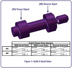
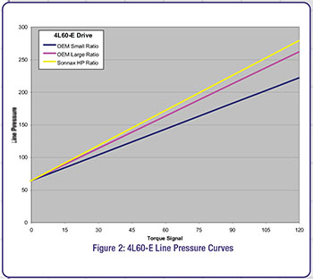
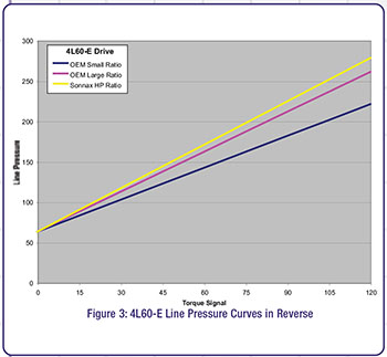
Figures 1, 2 and 3 illustrate how changes in the boost valve ratios affect the line pressure curve in a 4L60-E.
In Figure 1, the boost valve is shown and sizes indicated for the torque signal (ØA) and reverse (ØB) spools for the small and large OEM valve ratios, as well as the Sonnax improved ratio. The graphs in Figures 2 and 3 show that as the valve spool sizes increase (or as the ratio between the boost valve and the pressure regulator get larger in this instance), higher line pressures in Drive and Reverse are achieved.
 |  |
So, for vehicles with higher torque capacity or requiring increased performance, a larger ratio valve should be considered. In many instances when the OEM makes multiple ratios, Sonnax will make the largest or most popular size, or design a ratio for even higher line pressure if the unit is in need of more holding capacity.
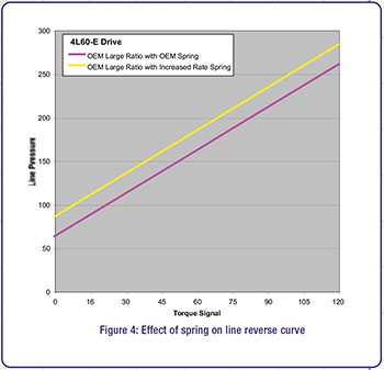
A common rebuild procedure is to alter the pressure regulator valve spring in order to change line pressure. While this modification does adjust line pressure, it should be noted that the slope of the pressure curve does not change, but rather it is offset by the same amount at both the low and high ends of the range (see Figure 4). By replacing an OEM 4L60-E large pressure regulator valve spring with a stronger spring, it can be seen that line pressure is increased by the same amount, regardless of throttle pressure influence.
Changing boost valve sizes and pressure regulator springs both have benefits, but when considering your part options, the important thing is to be aware of how they are different. Changing springs will generally increase pressure a consistent amount, while a larger boost valve will have a greater effect at high pressure and a lesser effect at low pressures.
 | 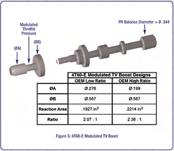 |
In the 4L60-E boost assembly, the larger valve ratios result in higher line pressure. This is because the larger valves have more reaction area to counter the pressure regulator valve, which stays the same diameter. However, a larger spool size does not always indicate higher boost or pressure. For instance, in the 4T60-E MTV boost valve assembly, the valve with the smaller spool diameter is considered the “high” ratio, resulting in higher pressures (see Figure 5). This is because modulator pressure is reacting on the difference between spools A and B. Assuming that spring forces and balance line area stay the same between the low and high ratio assemblies, modulator pressure would be acting on a larger area for the high ratio with the smaller valve spool. So the resultant regulated line pressure would be higher when using the boost valve with a smaller diameter. When swapping ratios during rebuilds, these forces and diameters should be examined closely to ensure that the desired effect is achieved.
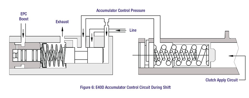 |
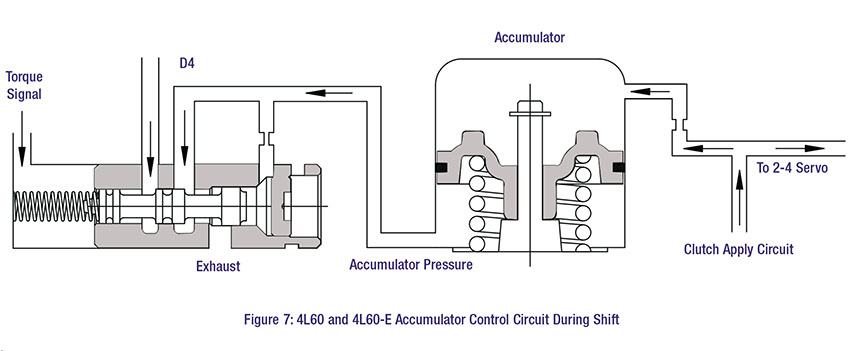
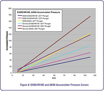
Accumulator control valves are another location where we find multiple valve ratios. The E4OD/4R100 and 4L60 & E/200-4R use various sized (different ratios) accumulator control valves to influence shift feel. As seen in the oil circuits in Figures 6 and 7, these Ford and GM valves are very similar in function. Throttle pressure, via EPC boost or torque signal, is used to influence the accumulator control pressure on the resisting side of the accumulator piston. Figure 8 shows the effect of these different valve ratios on the E4OD/4R100 and AX4N. The pressure curves show that as the plunger size is increased, the accumulator pressure control rises, which would result in quicker and firmer shifts.
 |
There are many other valve applications in which the OEMs use multiple valve ratios to tune a control pressure to best suit various vehicle applications. The AX4N bypass clutch control sleeve and plunger valve kit (pictured on page 152) has two known OEM valve ratios to adjust converter clutch apply. The 4R100 low/reverse modulator sleeve and plunger valve kit
(pictured on page 167) also has two known OEM valve ratios to adjust the holding capacity on the low/reverse clutch. Care should be exercised when replacing any worn sleeves in these locations, because using the wrong-sized valve for the vehicle could result in converter apply/release complaints (AX4N) or burned low/reverse clutches (4R100).
In some instances, Sonnax creates increased ratio replacement parts that provide pressures greater than the OEM design. These parts are typically created in order to overcome a chronic complaint or failure with the original design, or for heavy duty or performance applications. One example of this is the 77754-03K 4L60-E TCC regulator valve kit, shown on page 26. This slightly undersized valve (Ø.400" vs. Ø.440" stock) changes the ratio between the isolator and regulator valve, resulting in slightly increased TCC apply rate. This Sonnax modified valve ratio has approximately 10 percent higher TCC apply pressure, and has proven to be very successful on pre-EC3 units to overcome the common 1870 slip code set by low regulated converter apply pressure.
It should be noted that when Sonnax offers an oversized valve (pressure regulator, bypass control valve, etc.) for an application in order to refurbish the bore and eliminate wear, that all pressures and valve spool ratios have been considered. This is to eliminate any significant pressure changes as a result, and ensures that no adverse shift feel or component apply/release complaints will occur.
 | 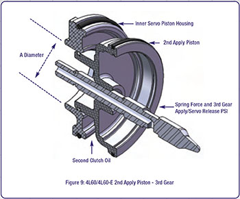 |
These same basic concepts of apply size vs. performance can be transferred to servo assemblies. As noted previously, on vehicles with larger engines, increased torque and therefore component holding capacity is required. For example, GM designed three different 2nd apply piston ratios for the 4L60 & E. Like the 4T60-E MTV boost valve mentioned previously, smaller means more area. When looking at the cross section of this servo assembly (see Figure 9), it is easy to see how a smaller piston “A” diameter results in larger apply surface area and increased holding pressure and force on the band.
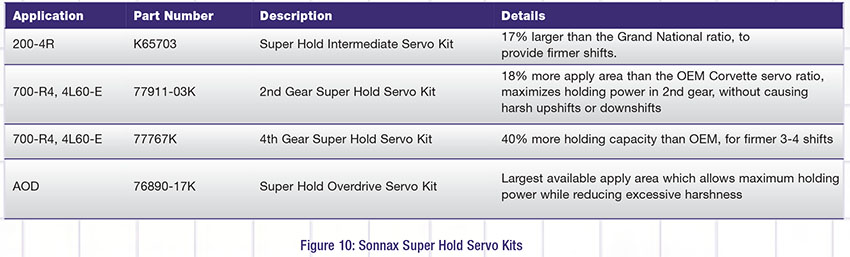
What might not be as obvious with this assembly is that the 2nd apply piston also functions as an accumulator for 3rd gear. The 3rd gear apply pressure and the servo return spring act on the release side of the 2nd apply piston to overcome 2nd clutch oil during a 2-3 shift. So the ratio between the apply and release side of the piston becomes critical to band and clutch timing. For optimal band release, the relationship between apply and release pressure forces on the servo must be maintained so that the servo release (3rd gear side) always has a greater force than the apply side. For many of the transmissions commonly used in high performance applications, Sonnax has designed “Super Hold” servo assemblies (see Figure 10) to provide significantly increased holding capacities and maintain optimal apply/release relationships.
 |
So when rebuilding a transmission, whether for street or high performance applications, take some time to ensure that the correct valve and servo ratios are being used for the specific vehicle. The durability and drivability of the transmission will be improved, and both you and your customer will be happier as a result.
Maura Stafford is a Sonnax project engineer and a member of the Sonnax TASC Force® (Technical Automotive Specialties Committee), a group of recognized industry technical specialists, transmission rebuilders and Sonnax Industries, Inc. technicians.
While Sonnax makes every effort to ensure the accuracy of technical articles at time of publication, we assume no liability for inaccuracies or for information which may become outdated or obsolete over time.