Whatever Turns You On: Is your TCC 'ON' until Oil turns it OFF or is it 'OFF' until Oil turns it ON?
Most transmission and torque converter rebuilders are familiar with the basic concept that the typical torque converter clutch is controlled with release oil, while clutch packs inside the transmission are activated with apply oil. Take your  average 4R100: The converter clutch is prevented from engaging the converter front cover because there is release oil being fed out of the tip of the input shaft, and this flow of oil keeps the clutch lining away from the front cover. Once that oil is turned off, then the clutch can press up against the cover and TCC lockup occurs. However, clutch packs inside the transmission case are engaged with an exactly opposite strategy. For example, the forward clutch in the 4R100 will only engage when apply oil is routed to the appropriate circuit, and oil pressure forces the piston to compress the clutch pack.
average 4R100: The converter clutch is prevented from engaging the converter front cover because there is release oil being fed out of the tip of the input shaft, and this flow of oil keeps the clutch lining away from the front cover. Once that oil is turned off, then the clutch can press up against the cover and TCC lockup occurs. However, clutch packs inside the transmission case are engaged with an exactly opposite strategy. For example, the forward clutch in the 4R100 will only engage when apply oil is routed to the appropriate circuit, and oil pressure forces the piston to compress the clutch pack.Big deal, you say. So the typical TCC is “normally on” unless there is oil to keep it off, while a transmission clutch pack is “normally off ” until there is oil to turn it on.
Well, the big deal is that there is, as usual, an exception to the rule. There are torque converter clutches out there that function similarly to the typical clutch packs used inside transmissions – the converter clutch is “off until it is commanded on,” not vice versa. Knowing the operational theory behind what you’re building and selling will help you build (and sell) a better product. If you sell these clutch pack type of torque converters to transmission rebuilders, then you just might be helpful in providing diagnostic hints when your customers have TCC-related complaints. Just think of your inherent value to your customer if you can do more than deliver converters and cash their checks!
Multi-disc Clutches vs. Clutch Pack-style Converters
Here is where it can get confusing. We are all familiar with the different multi-disc torque converters that are in the marketplace today. The E4OD/4R100 is the unit that first comes to mind, but there are others. There are also 4F50N, A4LD, 5R55N/S/W and various ZF units with more than one friction surface inside the converter. All of these converters work on the typical release oil theory – the TCC in all of these units will normally apply unless release oil is present to turn the clutch off. But clutch packstyle converters can (and usually do) have more than one disc. Therefore, while most clutch pack-style converters have more than one friction surface (disc), not all multi-disc converters are considered clutch pack-style units. Like we said – it can be confusing.
Just remember: Traditional single- and multi-disc lockup units use reverse oil to keep the lockup piston away from the front cover. The new “clutch pack” style units use apply oil that is confined and sealed with apply piston seals – just like a clutch drum inside a transmission.
What’s Old is New Again
The first torque converter with a lockup clutch made its appearance in the 3-band Borg Warner transmission used in Packard, Studebaker and Jaguar automobiles in the mid-1950s. The lockup clutch was a single-disc design, and was 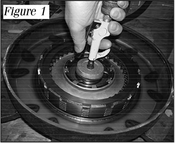 applied by a piston located in the cover. This first lockup was in fact a “clutch pack” type of unit – the TCC was normally off until oil turned the clutch on. Apply oil traveled through the center of the input shaft and exited behind the piston. The lockup was released by venting the apply oil to exhaust.
applied by a piston located in the cover. This first lockup was in fact a “clutch pack” type of unit – the TCC was normally off until oil turned the clutch on. Apply oil traveled through the center of the input shaft and exited behind the piston. The lockup was released by venting the apply oil to exhaust.In 1961 the first multi-plate lockup clutch was introduced, and this unit was also a clutch pack-style unit. This clutch was in the converter of the Buick Dual Path transmission, used in the Buick Special through model year 1963. The clutch was a four-disc design and was applied by a piston located in the cover. The apply and release circuits in the Dual Path were much like those found in the 3-band Borg Warner transmission.
From 1964 to 1977 there were no lockup torque converters introduced. During this period most of the charge oil circuits were similar. Charge oil would enter the converter between the impeller hub and the stator support, and exit the converter between the stator support and input shaft.
In 1978 Chrysler introduced its “new” lockup clutch. This single-disc design works on the release oil theory – this clutch will normally apply if there isn’t any release oil flowing through the tip of the input shaft. Torque converter clutches in autos and light trucks from virtually all makes and models worked according to this principle for more than 20 years.
In 1997, Daimler-Chrysler introduced a new breed of converter for use in the 722.6 transmission. Today, this transmission is used in many types of vehicles, from the sporty Chrysler Crossfire, to Mercedes Benz sports cars, sedans 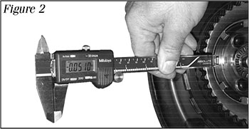 and SUVs, and even in hardworking Dodge and Freightliner Sprinter vans. When builders first started seeing 722.6 converter cores, they knew something was different because of the unusual profile of the converter front cover. Now Jatco has gotten into the act, and the converter in the RE5RO5A transmission used in Nissan and Infiniti cars, trucks and SUVs uses a clutch pack-style lockup. However, you can’t immediately see that the RE5RO5A core is a clutch pack style unit – the profile of the front cover is not quite as obviously unique as the 722.6.
and SUVs, and even in hardworking Dodge and Freightliner Sprinter vans. When builders first started seeing 722.6 converter cores, they knew something was different because of the unusual profile of the converter front cover. Now Jatco has gotten into the act, and the converter in the RE5RO5A transmission used in Nissan and Infiniti cars, trucks and SUVs uses a clutch pack-style lockup. However, you can’t immediately see that the RE5RO5A core is a clutch pack style unit – the profile of the front cover is not quite as obviously unique as the 722.6. From an OEM perspective, the benefit of a clutch pack-style converter over traditional lockup converters – single disc or multi disc – is that clutch capacities are much more “tunable.” Need more torque capacity? Just like transmissions, the OEM can add more clutches to the pack. Problems with damper spring capacity? A clutch pack that depends on apply oil is easier to cushion and modulate than a traditional torque converter clutch that operates on release oil. The TCC in clutch pack units are serviced like clutch packs in a transmission. Clutches, steels, pistons with lip seals – this clutch pack system is new stuff to converter rebuilders, but it is business as usual for transmission rebuilders. The apply pistons for the new clutch pack converters are located in the covers like their ancestors from the ’50s and ’60s, and they also share the earlier apply and release hydraulics. By applying air to the passage where the input shaft enters the cover, you can check the integrity of the pistoseals (see Figure 1). Applying air to this same passage will also help to check the clutch release clearance. The distance that the piston travels from the release to the apply position is the clutch release clearance (see Figure 2). Proper clearance should be .008" to .009" for each friction in the clutch pack.

Tell your customer that they can even use an input shaft to test the integrity of the hydraulic circuit in a converter that is welded together (see Figure 3). Transmission shops have been air testing clutch pack apply circuits for years and they will quickly understand what you are describing. Having the ability to “air check” the TCC on his bench will be a new diagnostic tool for the transmission builder. No air check method can be used effectively in traditional type lockup units.
The clutch pack style of TCC has come a long way since the days of the 3-band Borg Warner and 1961-63 Dual Path in the Buick Special. Today, the current units that are using a clutch pack-style TCC are the Mercedes 722.6 and the Jatco RE5RO5A – but there will likely be new units introduced that will use this type of TCC.
Knowing the operational theory of these “new” clutch pack-style converters will help you to build a better unit and help you to serve your customer. And who knows – you might even help diagnose a stubborn TCC problem in an old Studebaker!
While Sonnax makes every effort to ensure the accuracy of technical articles at time of publication, we assume no liability for inaccuracies or for information which may become outdated or obsolete over time.