“8” Ball, Center Pocket? Location and Function of New #8 Checkball for 6L80/90
Jim Dial
The 6L80/90 transmission is showing up in shops much more frequently than in the past, as vehicles equipped with this unit get older. Believe it or not, the 6L80 is already 10 years old! As time flies by and we get familiar with rebuilding a specific transmission, we store in our memory more and more details of the disassembly and reassembly of specific items — such as the pump, input drum and valve body — to the point where it becomes second nature. This particular transmission is a pretty easy build. After their third overhaul, most builders would tear down the internal components and dump everything into a basket, run it all through the parts washer and start rebuilding and reassembling after the parts are cleaned.
The same thought process typically goes for the valve body. First we disassemble the TEHCM, then split the valve body halves and remove the separator plate. Then we flip the halves over on the bench, dumping the checkballs and draining the excess oil in preparation of a thorough cleaning in the solvent tank. After the cleaning process, vacuum testing and replacement of worn valve trains, we start the assembly process by installing the seven checkballs into the valve body. The only issue here with the 6L80/90 is that there are eight checkballs lying on the bench, not seven! It turns out that — sometime in 2014 — changes were made to the separator plate and a checkball was added to address some concerns related to a clunking sensation during both acceleration and deceleration in 1st Gear. This is an odd complaint. It almost sounds like a low speed “lift foot” upshift of sorts, but this is not the case.
For 6L80/90, when Drive is selected from Park/Neutral, 1st Gear is commanded “with engine braking,” which means the low Reverse clutch is applied. A partial circuit diagram shows shift solenoid 1 is “ON,” which moves clutch select valve 2 to the left, connecting a passage from CBR 1/4-5-6 pressure to the low Reverse clutch apply passage (Figure 1).
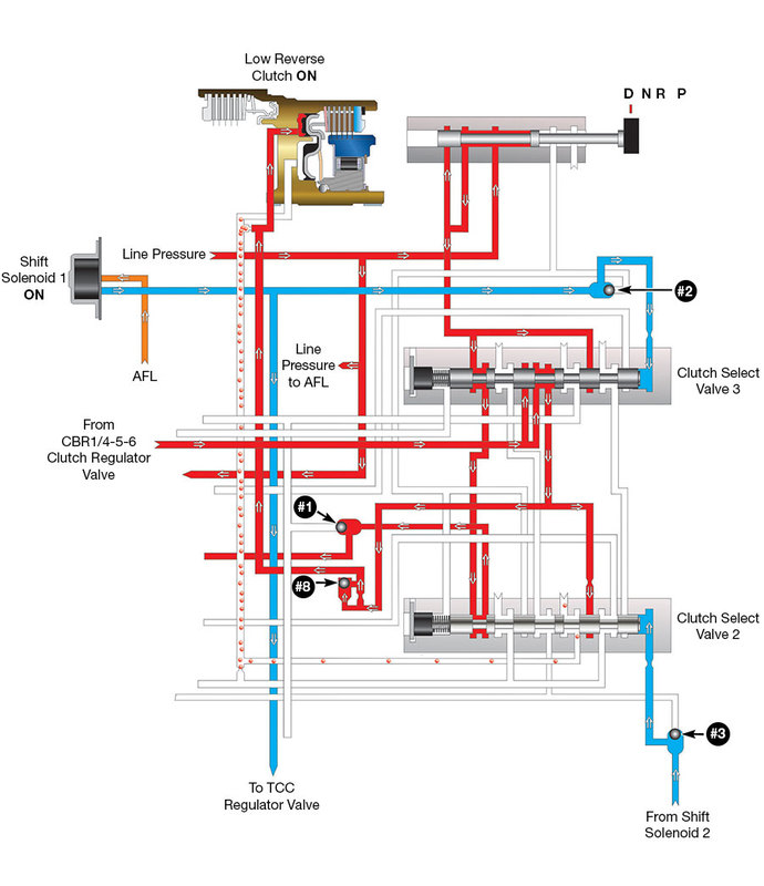
When the selector is placed into Drive from Park/Neutral, 1st Gear is commanded and solenoid 1 is energized to provide engine braking. Clutch select valve 2 opens connecting CBR1/4-5-6 clutch regulator pressure to the low Reverse apply passage through the #8 checkball, as shown in the circuit diagram.
Notice in Figure 1 that pressure is fed through our recently added newcomer, checkball #8. As vehicle speed increases, the TEHCM monitors inputs from various sensors to determine when to turn engine braking off before the 1-2 upshift (Figure 2).
| Figure 2: 2014-Later 6L80/90 1st Gear |
|---|
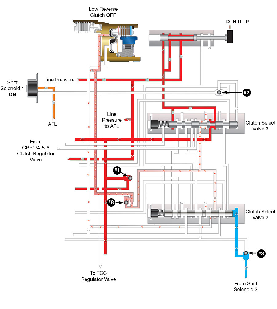 |
| As vehicle speed increases, the TEHCM monitors information to determine when to turn solenoid 1 off and energize CBR1/4-5-6 solenoid to block pressure to clutch select valve 2. This action allows clutch select valve 2 to move to the right connecting the low Reverse passage to an exhaust. The #8 checkball seats and forces this exhaust through an orifice, slowing down the release of the low Reverse clutch. |
We all know that if the low Reverse clutch is still on during a 1-2 upshift, we will have a severe bind-up. When the TEHCM sends the signal to turn “OFF” engine braking in 1st Gear, shift solenoid 1 is de-energized and CBR 1/4-5-6 solenoid is ramped up to block pressure to clutch select valve 2. This action allows clutch select valve 2 to move to the right by spring force, connecting the low Reverse passage to an exhaust. The #8 checkball seats and forces this exhaust through an orifice, slowing down the release of the low Reverse clutch. The added #8 checkball slowing down the rate of the low Reverse clutch can help make the transition from 1st Gear engine braking to 1st Gear a little more seamless. As you can see, the comparison of a low speed “lift foot” upshift is close to this complaint, but not the same because we are still in 1st Gear.
Refer to Figure 3 for the location of the new #8 checkball, which is near the center of the valve body.
| Figure 3: 2014-Later 6L80/90 Valve Body |
|---|
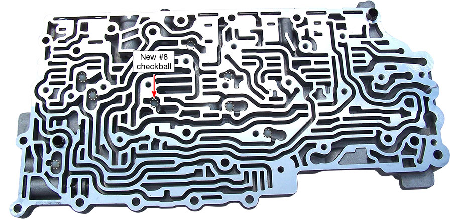 |
This pocket has always been there, but was always vacant until 2014. When the eighth checkball was added, the separator plate also changed (Figure 4).
| Figure 4: 2014-Later 6L80/90 Separator Plate |
|---|
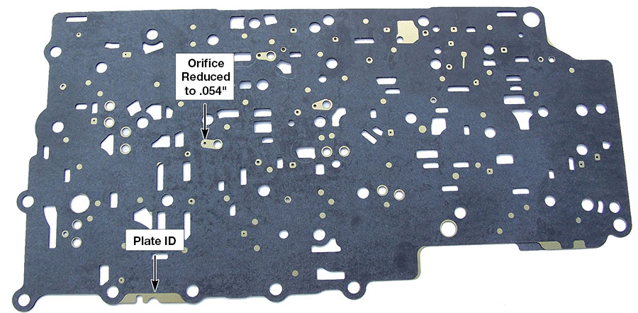 |
The orifice indicated was reduced to .054" to help slow down the exhaust of the low Reverse clutch during the transition from 1st Gear engine braking to 1st Gear. Figure 4 also shows separator plate identification for the ’14-later plate. General Motors provides a service package under part number 24272467 that includes the ’14-later separator plate and eight checkballs that will retrofit back to ’10-later models (Figure 5).
| Figure 5: GM Service Package, Part No. 24272467 |
|---|
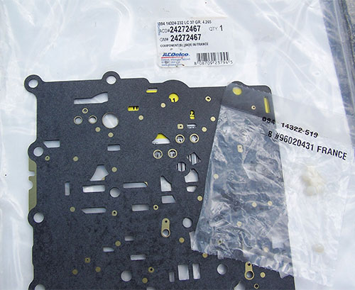 |
Installing this service package can help eliminate this complaint on ’10-later 6L80/90 applications.
Hopefully this information will help if you ever run into a question of where to put the eighth checkball. In this instance we are going for the center pocket — not the side or even the corner pocket.
Jim Dial is a Sonnax technical specialist and a member of the Sonnax TASC Force (Technical Automotive Specialties Committee), a group of recognized industry technical specialists, transmission rebuilders and Sonnax Industries Inc. technicians.
Related Units
While Sonnax makes every effort to ensure the accuracy of technical articles at time of publication, we assume no liability for inaccuracies or for information which may become outdated or obsolete over time.