Keeping Up with Torque: The Flanged Impeller Hub
Ed Lee
Flanged Impeller Hubs can Handle the Increased Output
The output torque of engines has been increasing over the years, and today’s engines are considerably more powerful than those of a few decades ago. As output torque has increased, so has the need to build stronger converters to harness the additional foot pounds of torque. One major improvement has been the introduction of the flanged impeller hub.
The flanged hub has two distinct advantages. First, it makes the impeller more rigid by adding anti-ballooning capabilities that aren’t possible with butt or through-mount hubs. This helps control the endplay deviations of the converter during heavy thrust loads. By keeping the endplay of the converter within the component’s ability to pilot the bearings, the life of the bearings is increased significantly. Secondly, the flanged hub gives the rear stator bearing a better surface to run against. It stays flat and true under high torque demand conditions and runs perpendicular to the centerline of the converter. This also increases the life expectancy of that bearing.
The flanged hub was first introduced on the AT540/545 converters and was immediately accepted. Replacing this hub became a routine procedure. The same cannot be said about the flanged hubs commonly used on a number of foreign-made converters. There seems to be something mysterious or taboo about the flanged hubs that are installed from the inside of these converters. But there is nothing mysterious or complicated about replacing these hubs as long as you follow a few basic guidelines.
First, you must remember that flanged hubs, unlike butt or through-mount hubs, are not held independently on the centerline of the converter when they are welded on. You must rely on the original pilot hole in the impeller to properly align the hub. For this reason, you must take extra care when removing the original hub to maintain the integrity of the pilot hole.
There are many different ways to achieve this. Two options you can use are:
Option 1
Holding the impeller in a lathe, machine the weld that extends above the top surface of the flange down to the flange with a regular carbide cutting bit.
This will be even with the surface of the impeller. Next, you need to know the O.D. of the replacement hub where it pilots in the impeller (see Figure 1). In this case we are using a [JA-90-9G] hub and the diameter is 3.250”.
 |
That measurement is the same as the I.D. of the pilot hole in the impeller. The height of the step on the replacement flange is the same as the thickness of the impeller. In this case the step is .170” (see Figure 1).
You want to have at least two-thirds of the thickness of the impeller remaining for proper centering after the hub is removed, so do not plunge-cut more than .055” deep when removing the hub. You will hear a distinct sound as the tool bit passes the diameter of the pilot hole, and that’s your clue that the weld has been separated. Use a piece of wood or a plastic hammer to tap the flange into the impeller. Remove the impeller from the lathe and dress the surface that the flange will rest against with a Scotchbrite™ pad disc in a small air grinder (see Figure 2). You are now ready to install
the replacement hub.
Option 2
Start with the impeller in a lathe and machine the weld down to the flange, as outlined in Option 1. Then, replace the regular cutting bit with a carbide parting tool (see Figure 3).
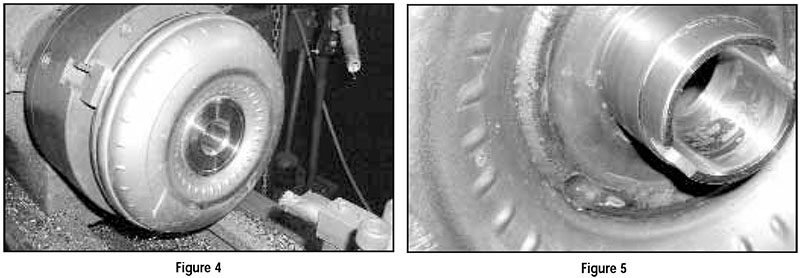
Plunge-cut with the parting tool just inside the finished I.D., which you have already determined is 3.250”. You will hear the flange ring fall into the impeller as you near the end of your cut. The rest of the hub will fall off as the tool bit finishes the cut. You will have to machine the bore to your finished I.D., and it’s a good idea to test-fit the hub from the outside as you go (see Figure 4).
 |
There are two types of flanged hubs, outside and inside mounting. A flanged hub will provide a new surface for a stator thrust bearing or plastic thrust cap to ride on. This new bearing surface must be parallel and at the same distance to the impeller blades as the original (see drawing below). To install flanged hubs the impeller must be first bored out and faced, so that the correct distance and parallelism is achieved, and then welded in place.
 |
Related Parts
While Sonnax makes every effort to ensure the accuracy of technical articles at time of publication, we assume no liability for inaccuracies or for information which may become outdated or obsolete over time.