Most teardowns start by coupling up the impact and finish with a set of “burned clutches” on the bench. If the cause is not obvious we take a chance or gamble on possibilities. The intent of this entire catalog is to change your gambling or luck locating the problem.into confidence, knowing you hold the winning hand. I agree that sometimes it is good to walk away, but only if a valve fights back or you run for a cup of coffee. With current transmissions more time is required on the controls. We will be following procedures to assist in locating the problem.
Disassembly
If electronic-related, test the resistance value as you wiggle the circuit before disconnecting. Crack the valve body bolts loose with a torque wrench first. Were all the bolts retained with the same torque? Flow-check the filter (in a solvent tank), and then break it open looking for traces of material or possible restriction. Remove the valve body and air-check the circuits, before dis-assembly. If a problem is unfamiliar, grab a book to prevent a (CB) Comeback, or Confused Blunder. Also review the partial oil circuits in this catalog and OEM circuits to better understand them.
Gasket Surfaces
(Figure 1) Look closely at the gasket for signs of undertorque or washed-out print patterns. Fading print patterns lead to cross leaks, delayed engagement or clutch distress. New gaskets are commonly .008" to .009" thick, and after proper torque crush to .006"- .007". Any imperfections such as a check ball marker (Figure 1, raised by .008") previous gasket (.007") or misaligned plate (threads catch the plate raising it by .012") would be beyond the retention of a standard gasket.
Valve Body, First Glance
In Figure 2 a number of problems became evident. The L retainer is not located properly (A) (No 4th gear), the cooler thermal valve is stuck shut (B) (fluid overheat, poor TCC) and the bathtub was punch marked (C)(possible cross leak).
Attention to details here may resolve a problem before going further. If you see the body has been tampered with, take a closer look. Are there pick marks on valve edges, which might cause them to hang (Figure 3)? If you see any such marks remove the valve, or at least stroke the valve through its entire travel. Never pry on the anodized edge of a valve, but only on the spool face (Figure 4).
Low Mileage: Never Touched, Nothing Wrong!
The pay attention flag should go up here! This might be the time you want to get a cup of coffee. The next questions are “Where do I start?” and “What’s the most effective use of my time?” First, I would review the Sonnax components designed to fix that complaint. But not all complaints have corrections designed for them yet.
If the problem is a loss of gear or shift code (Figure 5), examine power-flow and use the oil circuit to work from the element to the valves, as if using a road map and working back from the end of the trip. If the complaint was slippage, poor shift quality, delays, etc., then work through all regulation and line-rise circuits. With a TCC code or slip code, back-track
from the converter to the pressure regulator valve. A worn bore has fluid loss, and as operating temperature rises, so does the leakage and the effects from it. A hanging valve shuts off oil flow and loses a gear or TCC entirely. A mis-assembled valve body does anything it shouldn’t. Before you start to take it apart, clean it, dry it, and try to test it.
Inspection and Test Equipment
Inspection with the valve body assembled:
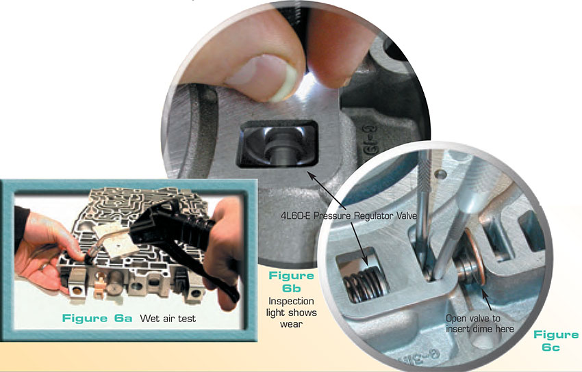
Throughout this catalog we have illustrations of air and visual movement testing. Clearance (less than .002") is required for an oil film to support the valve. Clearance on a dry air test is leakage. During a wet-air-test (Figure 6a), you pre-fill the area and force the fluid out. If the fluid blows through the gap with no delay, you have a problem. The key points here: the air pressure must be regulated to less than 30 psi. and the amount of fluid leakage should be minimal (this test utilizes experience and judgment). Test plates can be made to enclose circuits and the WAT works well to verify that check balls seat. The high intensity penlight works well for visual bore wear (Figure 6b).
A side-to-side valve movement inspection (Figure 6c) works well, as long as you place the valve in the position it operates in. No movement should be felt or seen in your prying tools. All raw aluminum valves (no anodizing) should be pulled for inspection.
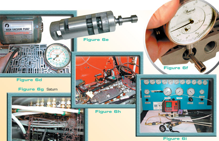
A vacuum test works well to obtain a definite good vs. bad value. This example (
Figure 6d) is on the
4L60-E AFL balance circuit. This type of test requires a good pump that will pull to 30". A hand held pump will not have enough volume, but your air conditioning station or an air-over-vacuum pump works well. This test must be done with the valve body dry, and tests all “captive” circuits in minutes before taking anything apart. A captive circuit is enclosed on each end and often works between two spools at shift valves or regulators. The 4L60-E pressure regulator valve can be tested for balance-wear and decrease spool to bore wear. Expectations? 26" to 24" is very good, 23" to 20" is questionable and needs inspection, and 19" or less has excess tolerance. You will find many bores that test less than 18" with severe visual bore wear.
The following tests require the valve body to be dis-assembled:
We commonly refer to a sag test, which can be either visual or measurable. You can visibly see the excessive clearance between the spool and the sleeve on this 4L60-E accumulator control sleeve (
Figure 6e). You can measure the sag or “deflection” (up-down movement) on many valves such as this
4T60-E converter clutch valve (
Figure 6f). Our instructions will note the pass-fail measurement when applicable.
Hydraulic test equipment:
Hydraulic test equipment isolates the valve body from the transmission. This equipment will identify leaks quite differently than noted above. Pressure readings are taken on each circuit and can be designed to simulate on-car operation. The Saturn valve body (
Figure 6g) is shown with “normal” operating oil loss and the 4L60-E (
Figure 6h) has a worn abuse plug (
77754-21) leaking critical 3-4 clutch oil.
The SonnaFlow
® (FM-01KA & [FM-03K]) can also be used with hydraulics to monitor the flow caused by a leak in the circuit. It has the accuracy to capture leaks as small as the
CD4E regulator balance circuit. It must be used with equipment supplying hydraulics, and requires a digital graphing multi-meter to capture the signal (
Figure 6i).
At this point, I’m confident you know where to start looking. Now we do what we do best, fix the problem. Methods of “going through” a valve body differ as widely as the Rinse-N-Go car wash versus a professional detailer. Nothing ever goes without a hitch, for an example, a wet floor is discovered. There is a choice to patch a rusted out floor pan with Fiberglass or cut out the old and weld in a new one. The outcomes are completely different. One fix is temporary, while the other is a durable reproduction. This catalog falls into the latter category, and the suggestions that follow are intended to help you detail the job. You may not use all the tools or procedures that follow, but they may stir your creativity.
Refinishing
There are several areas that require attention (
Figure 7). They may include gasket surfaces or valve bores. A flat stone, a machined flat plate or marble top with emery paper, work well for slight warpage and clean up conditions. A sharp single cut file with a minimum length of 16" can be used for severely dished surfaces. They should be finished on the flat plate. Be careful with honing type bore tools to prevent an out of round condition. If aluminum valves stick (do not force them, or they will fight back), use a bore sizing tool or smooth pin that closely fits the bore. The centering punches shown (
Figure 7) are a good investment as they serve a dual purpose. Their use in this case, is to tap on their shank and push contamination or size the bore. All the parts must be washed and rewashed after this dirty work. If a dent occurs from handling or a clip being out of place (
Figure 8), it can be peened/worked close-to-flush and finished off with Epoxy. Handle aluminum castings with care! The smallest dent can create later problems.
A rock can be a hammer or a wheel. A screwdriver can be a pry-bar or a chisel. A tool fits the need of the operator. To improve efficiency, I would suggest setting aside a special valve body bench. If you agree with the ideas listed throughout this material, equip the area with them. It is likely reaming is a part of your rebuild, shown below is a low cost reaming station (Figure 9b). The valve body is “lightly” attached to a plate, and a machinist coolant pump flows cutting fluid as you ream. Figure 9a identifies tools that should stay at the valve body bench. Starting from the top at 12:00 and moving clockwise:
Screwdrivers, (mini pry-bars) only to be used on the valve face, not to be used near an edge! The pick or scribe, should never to be used on the edge of an aluminum valve! A dental pick, (ask if you can keep it, when he’s done). A choke cable wire is very stiff and works great for getting to the bottom of things. Various wires for driving rods and for use as hole-fillers. Specially tuned chisels and flashlights. The small high-intensity, pen-type work best for inspecting bore wear. Wet Air Test plate. A gasket scraper, but only sharpen one side! Also pictured: a controllable air nozzle and various specialty adapters, specially tuned pliers, metal dressing tool for the de-burring of parts, magnets, jewelers’ files for hardness checking (Figure 10), threaded end plug pullers, a bore sizing tool, and alignment pins, which are required for proper reassembly.
Specialty Tools
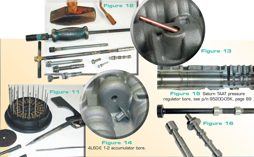
In Figure 11 a drill index with orifice type drills is pictured, and to its left a cut-off wheel to be used with the Dremel tool. Both are very useful. Under these are rollpin/spring-pin removal tools. They include a pick ground to a square end, stainless steel wire pounded flat, a drill bit tapered to a point or a welder can be used to remove these pins. If they fight back, some can be persuaded by tack welding onto them and pulling on the welded rod.
If the Valve Body Fights Back
Sometimes things just don’t go as smoothly as you hoped. The pullers in Figure 12 are for the sleeves or end plugs that refuse to come out. There are many possibilities here. The main thing is to get a good grip on the part. Many times you do not have to pre-drill but run a bolt or long handled tap into the part. These pullers can be fitted with nuts for your slide hammer. If they are stubborn, apply a “little” heat to the area around the part (not on the part being pulled). Use your judgment for the correct time and proper placement for the tool at the top of the figure.
Removing Sleeves or Stuck Valves
Some sleeves do not have open bores to screw into. In many situations like this, you can drill an access hole (Figure 13) that aligns with the sleeve or the valve and drive it out. The hole in this illustration is drilled from an angle through the bolt area. This access hole can be sealed, by resurfacing the casting or a brass compression washer under the bolt head. Some valves end in a blind casting (Figure 14). This circuit can be drilled to fit a blind head aluminum rivet and punched securely before valve install.
Inspecting the Bores
As mentioned previously, there are many ways to identify a worn bore. After removing the end plug, push the valve inward to the end of its travel. Does it travel smooth and does the spring compress without deflection? Now pull the valve out carefully, rotating it slightly as it exits. Does it catch at all? A catch is generally a worn bore or bent valve.
The bore pictured would not pass any of the tests described (Figure 15). Valves from discarded valve bodies can be tailored to become test tools. In Figure 16, a C6 modulator valve ([36833-01K]) and 4L80-E manual valve are trimmed to be used as sag or wiggle test tools. The 4L60-E pressure regulator valve (77917-07) has a rubber slide wiper seal installed into the balance hole. This allows you to vacuum test the balance circuit and decrease circuit without destroying the OEM part.
Precision Tools
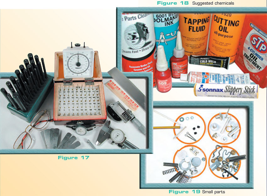
These are not required but useful (Figure 17). The pin gauges are used for orifice verification, the scale for recalibrating spring changes. Also illustrated are the straight edge, Plastigauge®, and other measuring instruments. The high magnification glasses work great for detailing and fine inspection. Purposes of the centering pin kit have been described earlier.
Suggested Chemicals
Most of the items listed are labeled for their use (Figure 18). The lapping compound can be used to bore fit or polish mating surfaces. Abrasive household cleansers work also. The Epoxy is used to fill dents and small orifices. The STP should be mixed 50/50 with ATF for valve, o-ring and sleeve assembly. They get as slippery as a bar of soap, so hold on. The Slippery-Stick™‚ retains valves and eases the assembly of o-rings.
Small Parts
The items in the lower right are samples of the Sonnax Small Parts Program(
Figure 19), found on pgs. 214-215. Items at the lower left are illustrated to suggest you tear down the cores you plan to scrap. If you have a trainee, this is a good way for them to gain experience. Items in the top left are very useful for repairs, shims and hole plugs. The washers are 2, 4, and 6 machine screws and the Allen screws are 10/32" x 1/8". The rod comes in very handy for driving out valves or plugging holes as mentioned before. The items at both top circles can be obtained from most hardware stores. The aluminum pegs in the top right are cable stops and work great for shims. Rivets are very handy and suggest as many sizes as possible.
Solenoids
Solenoids can be an article by themselves. A test procedure should be developed or purchased to closely duplicate their operating environment. If testing or equipment is not cost effective for you, then it’s best to replace them. The PWM enclosed canister type solenoids contaminate and do not flush easily. If the fluid and filters are dirty, it would be best to replace them. Shift solenoids can be tested, but again suggest OEM amperage and match their operating pressure.
Our Habits and Their Personality
Valve bodies seem to have their own personalities. Those with anodized valves don’t like to get pushed around. Valves under the influence of PWM solenoids loose control and feel worn out. If we push them and buff off their surfaces, they cross leak and the gaskets won’t seal. They like cleanliness, because if we stick them in a dirty cleaning machine they refuse to work. One comforting thing, they do appreciate attention from a torque wrench.
Bob Warnke is vice president of technical development and a member of the TASC Force® (Technical Automotive Specialties Committee), a group of recognized industry technical specialists, transmission rebuilders and Sonnax Industries Inc. technicians.