CD4E Transmission: Inspection Checklist
Bob Warnke
“Freeze…. Put the impact gun down and move away from the Tranny Jack.”
Wouldn’t it be great if there was a special “Comeback Prevention Unit” that would stop us from making our own jobs more difficult? Along with many other modern units, the CD4E is prime example of the challenges we are faced with in the transmission rebuilding industry. Today’s successful transmission rebuilds require a careful and thorough two-step process.
Diagnosis requires finding the cause as well as the failure. Repair requires correcting the initial cause in addition to repairing the damage. Once the unit is out and on the bench you have a good chance of finding failed or damaged parts but a far more difficult job of determining what caused the failure. Learning as much as you can before you go in will get you headed in the right direction more quickly, and will greatly increase the accuracy of your final diagnosis and repair of what caused the failure.
Many of the more common issues found on CD4E units leave an indication of what caused the problem. If you know what to look for and how to spot them, the indicators will guide you to the cause. In order to know where to begin looking when you get inside, learn as much as you can from the outside.
Using the specifications and information shown in Figures 1 through 6, and the diagnostic procedures listed below, many CD4E internal problems can be diagnosed. These diagnostics provide a Complaint, Test Procedure and Indicators to help you spot and identify some common problems. Pressure readings and cooler flow readings, as measured with a SonnaFlow®, are common starting points for your investigation. Additional test or inspection methods are also included.

Complaint:
- Delayed engagement
Test Procedure:
- Line pressure test at idle
Indicators:
- Low line pressure = Worn pump or filter problems
- High line pressure = Worn P.R. bore causing high line or failsafe high line cutting off converter charge
Complaint:
- No movement
Test Procedures:
- Cooler flow test
- Line pressure test – check for rise with increased load
- Measure converter movement when bolting to flex plate
- Measure pump shaft
Indicators:
- Low flow = Pump or filter problems
- Line pressure should vary with engine load. No change = P.R. valve problem
- Converter movement from fully pushed into case to pulled up against flex plate is over .100" = Converter finished build height too low, wrong converter or wrong flex plate
- Measure pump shaft: 4 cylinder is 14", V6 is 14 11/16"
- Long shaft in a 4 cylinder = blocked oil flow
 |  |
Complaint:
- 2-3 flare
Test Procedures:
- Line pressure test – check for rise with increased load
- Inspect servo travel
- Air test at case
- Other inspections
Indicators:
- Line pressure should vary with engine load. No change = P.R. valve problem
- Servo over .120" max = Excess travel, correct with selective pin
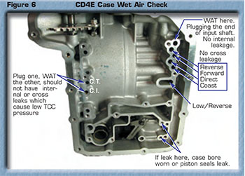
- Air test case as shown in Figure 6. Leakage = bore wear or hard seals

Other Inspections Check For:
- Worn Line pressure modulator bore
- EPC Solenoid function and adjustments
- P.R. bore – wear at large diameters or dirty/stuck pressure relief valve
- Dirty aftermarket EPC blow of used in place of standard end plug
Complaint:
- Bind up conditions
Test Procedures:
- Line pressure test
- High line verification test
- Air test/inspection
Indicators:
- High line pressure = worn PR or EPC solenoid failsafe condition. Perform verification test. Good line pressure = perform air tests & inspection
Verification Test:
- Using an external controller with the ECU isolated to prevent shift/EPC control, check line pressure. High line still present = PR valve worn or stuck
Air Tests & Inspection:
- Remove the valve body and air test feed circuits as shown in Figure 6
- Air test & inspect the drums for cracks
Complaint:
- Wrong gear starts
Test Procedures:
- Install shift controller to control the commanded gear
- Valve inspections
Indicators:
- Shifts correctly with controller = wiring/connection issues or possibly ECU mismatched to unit
- Wrong gear starts remain when using controller = Possible valve body failure or valve body mismatched to ECU & unit
- Inspect 1-2 shift valve bore (inboard end) for wear
- Inspect solenoid regulator bore for wear
Complaint:
- Harsh shifts
Test Procedures:
- Line Pressure
- High line verification test
- Inspection
Indicators:
- High line pressure = worn PR valve or EPC solenoid failsafe condition. Perform verification test (see Bind up conditions above)
- Good line pressure = inspect accumulator pistons for seizure (see part numbers 73840-24, -LR, -FWD
Complaint:
- Bushing failure
Test Procedures:
- Check cooler flow
- Inspect and update valve body and plate
Indicators:
- Low cooler flow = potential lube failure and bushing damage cause
- Bypass cooler and recheck flow. Substantial increase indicates blocked cooler
- Update the P.R. valve, converter regulator valve and separator plate. Install Sonnax part numbers 73840-RK and 73840-BK and perform plate modifications as instructed in the kits
- Add a ground strap from transmission case to battery to prevent arcing damage to bushing surfaces
Complaint:
- Code 628,1741-1744
Test Procedures:
- Pressure Test at CT port (see Figure 2)
- Cooler Flow Readings
Indicators:
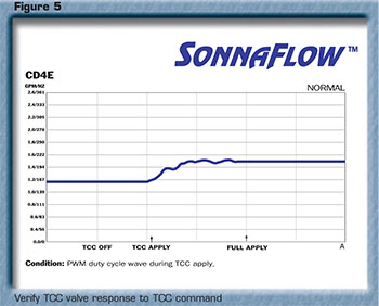
- Check CT pressure through all ranges and speeds as described in Figure 4
- Correct CT = Readings as indicated in Figure 4
- CT should rise sharply at TCC apply
- Low CT = (Most common causes): Valve body wear, worn pump or blown gasket, cracked TCC piston or worn bushings. Primary cause of valve body related issues is Bypass Clutch Control Valve wear. See Figure 1
- The SonnaFlow® with a Graphing meter can be used to verify TCC command was followed by TCC valve movement. (See Figure 5)
- Use line pressure and SonnaFlow® together, to verify pump condition
- High CT = Check P.R. and converter control circuits. A restricted cooler circuit will also raise CT pressure
Complaint:
- Erratic TCC Codes
Test Procedures:
- Check CT pressure during TCC apply.
- Inspect TSS Sensor
Indicators:
- A slow or rapid drop in pressure after apply (approx. 15 psi. or more) is often caused by a converter with internal leakage or a cracked piston
- Verify TSS sensor style. Later design (white) sensors, when used as a replacement for an early design (black) sensor, will often cause codes under certain conditions and may often be responsible for hard to duplicate codes
The pump, converter apply circuit, converter friction material, internal seals and the TCC solenoid can all be tested while the unit is in the car by performing a Shift Controller Stall Test. This stall test is not a WOT brake stall, where the engine stabilizes at 2500 RPM. The following “engine kill or stumble” test isolates the TCC lining and hydraulic control.
Shift Controller Stall Test on TCC Circuit (Cool Unit):
- Remove the air cleaner housing, wire retainer and transmission case connection
- Clearing codes can be avoided by attaching a solenoid block (OEM circuit) onto the chassis harness
- Install the Shift Controller to the transmission
- Jumper wires are an option. They are time consuming and alter the result, because of no EPC control
- Control EPC amperage to simulate OEM idle pressure
- Shift controller to 3rd gear (SS1 and SS2 off)
- Position selector lever in D, idle at 750 RPM
- Command a two second TCC apply (excessive test can cause TCC over-load or solenoid failure)
Indicators:
- Good converter: Engine will stall or near stall immediately on TCC apply (A 4 cylinder should stall, V-6 near stall)
- Weak converter: No noticeable change in RPM drop. Converter damper assembly often starts to rattle
Test Procedure:
- Road test with Shift Controller at operating temperature
- Command TCC in 3rd with light acceleration and during deceleration
Indicators:
- Good Converter: Engine RPM should drop sharply and have engine braking during coast down. At a stop, with brakes applied, command 3rd gear. Engine should pull down at least 150 RPM or cause stumble
- Weak Converter: No drop in engine RPM or engine braking felt
Converter Bench Test
- Good turbine hubs: The oil will run away as fast as it’s poured in
- Worn turbine hubs: The shaft will fill and oil will not drain past the bushing for 10 seconds or more
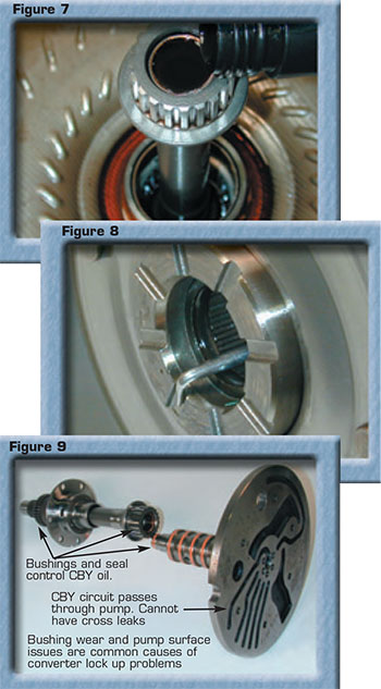
- Verify turbine slot depth is sufficient, by inserting a 90° seal pick at the face of the hub. The wire diameter at the angle of your pick must be between .072" to .082". The slots on a good converter are .078" – 082" (see Figure 8).
- Worn down hub slots: .072" thickness of pick will not side into worn slot
- Good hub: Pick fits
- With the converter lying on the bench and your pick hooked under the turbine hub, lift up on the pick to identify assembled endplay. Endplay should not exceed .050".
These turbine hubs are common to wear, restricting CBY/release, creating engine stumble at idle or TCC codes. Bushing wear and pump surface issue can also affect converter pressure (Figure 9).
Bob Warnke is vice president of technical development and a member of the TASC Force® (Technical Automotive Specialties Committee), a group of recognized industry technical specialists, transmission rebuilders and Sonnax Industries Inc. technicians.
Related Units
While Sonnax makes every effort to ensure the accuracy of technical articles at time of publication, we assume no liability for inaccuracies or for information which may become outdated or obsolete over time.