April 26, 2016
Understanding & Overcoming the Powerglide Servo Pin Bias Effect - Part 1
Note: Read Part 2 of this article for more in-depth technical information and a closer look at how the Sonnax Smart-Tech ratio-style servo kit completely eliminates the Powerglide pin bias effect.
Unexplained band failure in Powerglides can be overcome by addressing the servo pin bias effect. Although popular wisdom holds that high clutch oil pressure releases the servo on a 1-2 upshift, in reality – whether in low gear or high gear – there is ALWAYS some apply force on the servo pin. When in high gear, this apply force can be enough to overcome the return spring, preventing a clean release of the servo and allowing the band to drag and burn. This is the pin bias effect, true source of “mystery” band failures that cause crucial power to be lost when it’s most needed to propel the car down the track.
As shown in Figure 1, typical modern servos like the C-4, C-6 and 4L60 are designed with a smaller apply area and larger release area – a proper reaction area ratio that ensures the band will fully release. The Powerglide servo doesn’t work this way: it’s an older design with an equal seal diameter for both the apply and release sides. This doesn’t mean the forces are equal, however, as the release area excludes the .3 sq. in. area of the pin bore diameter. The result is a larger apply area and smaller release area – an improper reaction area ratio also known as the pin bias effect.
| Figure 1 |
|---|
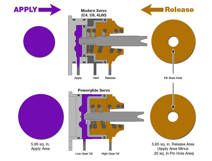 |
| The servo pin bias effect occurs when apply area is greater than release area. | |||
|---|---|---|---|
| Apply Area | Release Area | Reaction Area Ratio | |
| Powerglide Servo | Larger | Smaller | Improper 1.05:1 |
| Typical Modern Servo | Smaller | Larger | Proper .4:1 - to - .8:1 |
In normal operation, line pressure acts on the apply side in low gear and on both apply and release sides of the servo in high gear (Figure 2). In modern servos, there is greater force on the release side to overcome apply force, so little assistance is needed from the servo spring to release the band. Due to the pin bias effect built into the Powerglide servo, however, apply force can ONLY be overcome by the servo spring. At higher pressures, weak factory springs and some lighter aftermarket springs do not have enough force to fully retract the servo. The band will not be applied, but will not be fully released either, causing it to drag and overheat.
| |
|---|---|
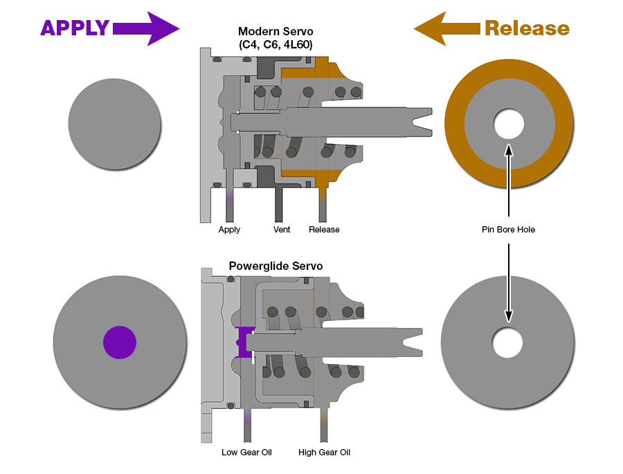 | |
At 250 psi, the pin bias effect built into the Powerglide servo design becomes dramatically apparent.
|
Applying This Information
This chart (Figure 3) shows the pin bias force in the apply direction when line pressure is present on both sides of the servo in high gear. For the servo to move to the released position in high gear, spring force must be greater than the pin bias force shown. The higher the line pressure, the greater the spring force required. This has diminishing returns though, because as horsepower and torque increase, there is a need for higher line pressure to hold the band in low gear.
| Figure 3: Powerglide Servo Pin Bias Formula | |||||
|---|---|---|---|---|---|
| Line Pressure in High Gear | 100 lbs. | 150 lbs. | 200 lbs. | 250 lbs. | 300 lbs. |
| "Bias" Force in Apply Direction | 31 lbs. | 46 lbs. | 62 lbs. | 77 lbs. | 92 lbs. |
5.95" Apply Area - 5.65" Release = .3 sq. in .3" sq. in x Line Pressure = BIAS FORCE | |||||
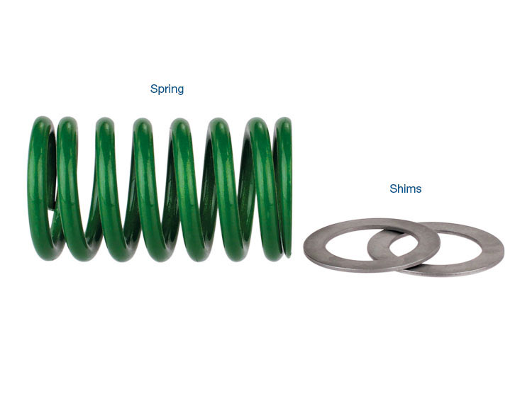
With stock-size servos, ensure the servo release spring used is strong enough to counter the pin bias effect at the line pressure being run.
Example:
Pin diameter = .625" with .307 sq. in x 250 psi = 77 lbs. force in apply direction with line pressure on both sides of servo in high gear. This means the servo release spring must be greater than 77 lbs. of force when servo is in applied position. With servo released (at rest), the installed spring height is about 2.280" (this can vary with some aftermarket cases). The servo adjusting screw is 20 threads per inch or .050" per turn.
If the servo is adjusted three turns out for a minimum of .150" servo travel, the spring height is reduced from 2.280" installed height to its working height of 2.130". This means that – at a height of 2.130" – the spring must have at least 77 lbs. of force to be able to fully release the servo at 250 psi. Not all springs will be strong enough. Higher line pressure will require an even stronger spring.
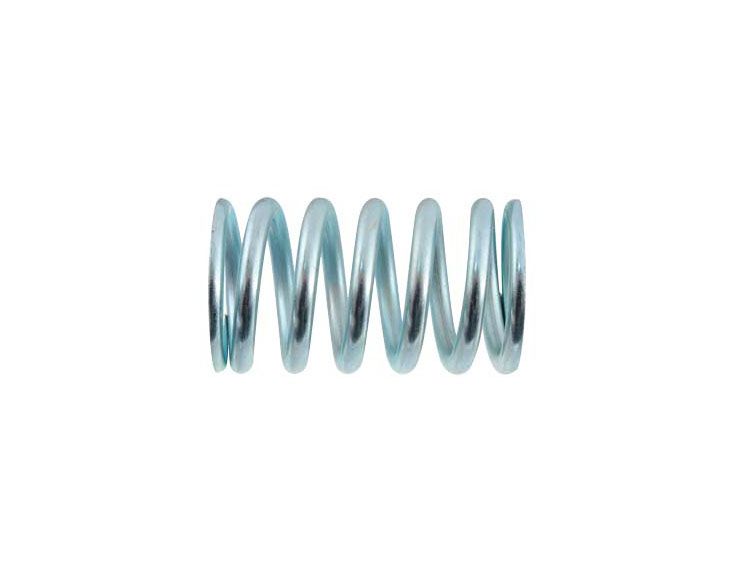
Veteran builders have learned that a strong return spring is required to keep a band alive.
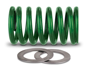 The Sonnax race-calibrated servo return spring kit 28133-HD is the only aftermarket spring specifically designed to offset the pin bias effect at line pressures from 200 to 275 psi. Compared to typical OE springs, 28133-HD has more spring force at rest and – due to its lower spring rate – less spring force in the applied position. The result is greater total band apply force and a fully released band in high gear.
This video shows how the Powerglide servo performs at high pressures when fitted with an OE, light aftermarket or Sonnax race-calibrated spring. It dramatically shows the pin bias effect in action, and why overcoming this built-in design flaw of the Powerglide servo is the only way to prevent “mystery” band failures.
Tuning Tips
Band Adjustment (if all else remains the same):
- More turns out of adjuster sets the servo deeper into the case when applied and increases release spring tension for quicker initial release.
- Fewer turns out of adjuster sets the servo less deep in the case and decreases release spring tension for slower initial release.
Line Pressure (if all else remains the same):
- Higher line = slower release of the servo (due to pin bias effect) and quicker apply of the high clutch.
- Lower line = faster release of the servo (and slower apply of the high clutch).
 Stop Struggling with the old Powerglide servo design!
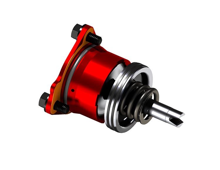
The Sonnax Smart-Tech ratio-style servo kit advances the Powerglide transmission to new levels that back up extreme horsepower with never-before-seen reliability. If you've upgraded other components and are still struggling with servo-related problems, the Smart-Tech servo is a key piece to solving this puzzle. Read Part 2 of this article for more in-depth technical information and a closer look at how the Smart-Tech servo completely eliminates the Powerglide pin bias effect.
For applications where ultimate holding force is required or when line pressure is reduced for efficiency, the Sonnax super hold servo kit 28821-09K has the greatest apply area of any servo but still has a strong return spring to deal with pin bias effect.
Learn More
January 25, 2017
Understanding & Overcoming the Powerglide Servo Pin Bias Effect - Part 2
May 09, 2017
From the Bench: Building a World‑Class Powerglide Racing Transmission
August 23, 2017
First, Do No Harm: Things You Should Know about Performance Servos
Gregg Nader
Related Units
Related Parts
While Sonnax makes every effort to ensure the accuracy of technical articles at time of publication, we assume no liability for inaccuracies or for information which may become outdated or obsolete over time.