Embracing Change
A doctor takes his car to a mechanic and complains "Your fee is more per hour then we get for medical care." "Yeah doc," the mechanic replies, "But your models haven't changed since Adam and Eve, and we have to stay up-to-date with new models coming out every month."
How true is that! It seems that no sooner have we wrapped our heads around how the "new" model or component functions than we find them taking a backseat to something even "newer." As Bob Dylan sang in 1964, "…for the times they are a-changin'." That was the same year that Ford introduced their C-4 Cruise-O-Matic with one of the industry's first aluminum cases, and when rebuild prices and financing were much different than today.
In the automatic transmission industry, huge changes have occurred over the past 40 years and now seem to be happening at an ever-increasing rate. To stay in business and be profitable, it's critical to acknowledge and understand these new technologies. Benjamin Franklin said it best: "When you've finished changing, you're finished." In other words, those who don't adapt to and adopt change will limit their potential and soon be shutting their doors for good.
In the mid-to-late-1980s, transmissions started incorporating electronics, first with simple pressure switches, then on-off solenoids, computers and various sensors. More recently, Pulse-Width Modulated (PWM) type solenoids were introduced in some applications so that pressures could be modulated. Now, many of these PWM solenoids are being updated to linear solenoids for pressure control.
There are a number of differences between PWM and linear solenoids, but the primary one is in their basic principle of operation. The PWM solenoid – usually operating at a low hertz frequency – has both the hydraulic and mechanical systems average the pressure and flow pulsations created by the solenoid duty cycle. This results in the control pressure and flow rate being more susceptible to variations in duty cycle. The linear solenoid – generally operating at a high hertz frequency – uses only the electronic and magnetic parts of the system to average the duty cycle, while the valve spool hydraulically balances control pressure and flow rate. This results in very little pressure and flow rate variations as duty cycle changes. Other differences are noted in Figure 2.
| Figure 2: PWM Solenoids vs. Linear Solenoids Advantages/Disadvantages |
PWM Solenoids | Linear Solenoids |
|---|---|
|
|
Most "newer" components have advantages and disadvantages over the previous design, so let's take a closer look at PWM and linear solenoids to understand the functional changes that have occurred over the years and how those changes impact your rebuild procedures.
PWM vs. Linear Solenoid Function
PWM Solenoids

A typical PWM solenoid is essentially an electronic pressure regulator valve (Figure 3). The solenoid shown below from a 4T60-E is used to convert PWM feed (line pressure) into the PWM signal used to control converter clutch apply pressure. This is accomplished by the following process:
- The Powertrain Control Module (PCM) sends on/off signals at 32Hz (32 times/second) to the solenoid.
- The on/off signals change the current through the coil assembly (electromagnet), altering the magnetic force on the meter- ing ball.
- Metering ball changes affect the controlled leakage of PWM feed fluid, which controls the resultant PWM signal pressure sent to the isolator valve.
The ratio of on/off signal time at the solenoid is referred to as the duty cycle and ranges from 0 to 100%. This ratio of on-time during a cycle (in this case, 1/32 of a second) controls the leakage and alters the pressure. Pressure is inversely proportional to duty cycle. When fully energized, or 100% duty cycle, PWM pressure is at a minimum, resulting in minimum converter clutch apply pressure. When the normally open solenoid is at 0% duty cycle, full PWM feed (line) pressure flows through the solenoid and strokes the converter clutch regulator to allow maximum converter apply pressure. The duty cycle often is between these two extreme percentages, as the computer continuously monitors vehicle speed, gear range, throttle angle and other parameters to adjust the duty cycle and allow a controlled slip apply or release of the converter clutch.
Linear Solenoids
 |
Now let's take a look at a TCC lockup pressure control linear solenoid valve from an AW55-50SN (Figure 4). This style solenoid also uses pulse-width modulation and functions electrically much like PWM solenoid in Figure 2.
- A signal from the Transmission Control Module (TCM) is pulsed to the solenoid at 300Hz with a varying amount of on/off time.
- The current through the coil assembly creates the electromagnetic force that moves the plunger in or out against spring force to adjust the position of the spool valve (housed in the long cast aluminum snout portion of the linear solenoid).
- The spool valve hydraulically regulates pressure control by balancing the internal forces.
When the solenoid current changes, the force generated by the solenoid changes causing the valve to alter the control pressure until a new balance point is found. The control pressure is proportional to input current. For this particular linear solenoid, increased current results in the plunger moving toward the snout which then moves the spool valve to an increased control pressure position. This then sends TCC signal pressure to the lockup control and relay valves, resulting in apply of the converter clutch.
Linear solenoids are becoming more common in late model transmissions, taking the place of PWM solenoids to control pressure. Aisin Warner uses linear solenoids in 5- and 6-speed units to provide a pilot pressure for controlling converter clutch apply and release, for influencing line pressure with a solenoid-generated electronic pressure control (EPC) and for controlling clutch pressure.
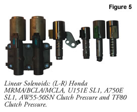
These types of applications and linear solenoids also are being successfully used in Honda and Toyota transmissions, although there are significant differences in design (Figure 5). Many of the Honda linear solenoids are integrated into a cast aluminum manifold that is bolted externally to the transmission case. The Aisin Warner and Toyota linear solenoids have the snout crimped to the electronic can and are mounted in the valve body bores.
It also should be noted that – with the new transmissions – the design of the solenoids is getting smaller. Not only does this provide weight and space savings for the valve body, but manufacturing costs are reduced as well. Most of the control valves are being designed smaller and switched from steel to aluminum to make them much more reactive and capable of effective operation at higher signal frequencies. Making the snout and the valve out of similar materials also allows for the same hydraulic clearance at variable temperatures, which provides better response time and reliability.
Reuse, Rebuild or Replace?
Understanding how something works is often the first step in knowing how to diagnose a malfunction. Linear solenoids tend to be more expensive than the simple PWM solenoids, so the choice of whether to re-use, rebuild or replace these parts needs to be made. There is no universally right or wrong decision. Ultimately, you will balance the needs of your customer, the cost of your time and your warranty structure and costs. Because the PWM and linear solenoids operate the same electrically, standard techniques can be used for both to determine electrical integrity. With the addition of the hydraulic spool and valve portion of linear solenoids, however, additional areas for failure need to be checked.
Check for Damage at the Cast Snout Flange & Plastic Connector
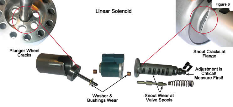
A quick check of the cast snout flange and the plastic connector should always be at the top of the list, as these areas tend to crack and break during the handling and shipping of valve bodies (Figure 6). Like other valve locations, the integrity of the bore-to-spool clearance is critical in maintaining the proper hydraulic sealing in order to maintain pressures. Visual wear can be seen in some instances, and some solenoids are designed so that the valve and spring can be removed for better inspection. Care should be taken in disassembly, though, as the snout end cap is sometimes designed as a tunable component for setting specific pressures at the factory during assembly.
 |
Establish Base Measurements
Taking measurements and/or marking the solenoid prior to disassembly is a must for ensuring proper recalibration. Using the valve body as the manifold and performing a vacuum test on the solenoid spool valve is a quick way to determine hydraulic integrity. Keep in mind that the integrity of the snout to valve body casting interface also is being tested, so vacuum numbers may be lower than a typical valve-to-bore check.
Open, Re-Crimp & Clean
Other components of the linear solenoid subject to wear or damage include the plunger, bushings and washer, but these cannot be seen and examined without taking the solenoid apart. There are aftermarket tools available that allow you to open and re-crimp the solenoid/snout to inspect these components and clean debris from the solenoid. Companies also are now entering the aftermarket with rebuilt and tested solenoids as well as newly designed replacement solenoids.
Solenoid Modules & Mechatronic Units
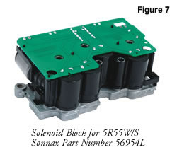
Not only is solenoid functionality changing, but their valve body integration method is evolving as well. Typically solenoids have been held in the valve body casting by a mechanical retainer, often at the outer bore of the valve that it was actuating. But in some of the newer transmissions (6L80-E, 6T70, 6F50, 5R55N/S/W, 42RLE, 45/68RFE, 62TE) we are seeing most, if not all, of the solenoids being bundled together into their own module (Figure 7). Whether OEM calls it a solenoid body, block or pack, this module is then bolted onto the valve body. In most instances, other pressure switches and sensors also are incorporated into these solenoid modules.
From a factory standpoint, the modular design provides many advantages over the use and assembly of solenoids as single components:
- It significantly reduces or even eliminates the amount of wiring and redundant parts. Now the OEMs can pre-wire components, incorporate circuit boards, use a single connector back to the computer, reduce overall valve body size, make modules adaptable to various transmissions and pre-calibrate the blocks to specific vehicles.
- Damage to the sensitive electronic components can be reduced during assembly, shipping and handling when they are put into a module instead of being installed individually.
- It is more advantageous for testing purposes to keep the solenoids bundled, as the modules can be pre-tested prior to assembling onto the valve bodies. This also reduces the time spent diagnosing electrical versus mechanical or hydraulic issues in the event of a failure, which reduces cost and the potential for damage or failure due to lengthy wiring and unprotected connectors
While this module design is great for the OEMs, it can be daunting from a rebuilder standpoint. Gone are the days of replacing individual solenoids or sensors due to failure. Modular solenoid blocks must be replaced as a unit, even if only one of the components has failed – a pricey proposition. As often happens when challenges arise, though, this has opened the doors for ingenuity. Companies are developing methods for rebuilding these solenoid blocks and filling a need in the aftermarket.
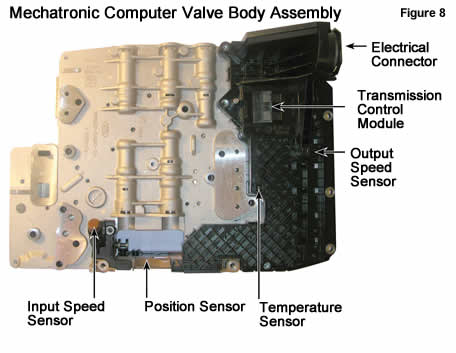
The likes of ZF (ZF6HP19/26/32 series, 6R60) and Jatco (RE5R05A) have taken the module approach one step further: they have incorporated all of the benefits of the solenoid/actuator module and combined the computer and the valve body into one assembly (Figure 8). Known as a "mechatronic" unit, this design provides yet another level of cost savings for the factory, both in manufacturability and testing:
- The ability to tune the computer parameters for each valve body and solenoid module allows the factory to loosen manufacturing tolerances on those components, thereby reducing cost and allowing the computer to compensate.
- Since the computer, actuators and valve body can now be tested as one mechatronic unit prior to final vehicle assembly, reduction in post-testing and modifications/rebuilds can be eliminated due to earlier detection.
- The mechatronic unit also can be precisely calibrated for the specific vehicle in which it will be assembled, providing much better drivability characteristics.
All of these factory benefits from mechatronic units create new headaches (and opportunities) for the aftermarket. As with the ZF 6-speeds, since the computer is calibrated to the vehicle, swapping out an entire mechatronic unit for a used core will not work. Some manufacturers permanently mount the computer to the valve body. The ZF design allows you to separate them, making it possible for the valve body portion (hydraulic and mechanical functions) to be changed or rebuilt as long as the base type (19/21/26/28/32/34) remains the same, but the computer needs to stay with the vehicle. Thankfully the ZF computer portion of the mechatronic is easily removable and fairly durable, but handle with care! Electrostatic discharge can leave you with a very expensive paperweight.
Reading into the tea leaves of these transmission changes, it seems the future is going to hold a lot more electronics, modular components and international designs that can be made to fit different vehicles with slight changes. All this leads to transmissions tuned for specific vehicles at the factory. Does this make our job more difficult? You bet! But with change comes opportunity, and what you want to make of that charts your own destiny.
So who knew that Bob Dylan was transmissionally clairvoyant back in the '60s when he sang, "If your time to you is worth savin', then you better start swimming, or you'll sink like a stone, for the times they are a-changin'." Or, if you prefer a more modern song and upbeat attitude, put on some Sheryl Crow, 'cause: "a change will do you good." So, I guess, "The only thing that stays the same is change." Wait, I've got more…
While Sonnax makes every effort to ensure the accuracy of technical articles at time of publication, we assume no liability for inaccuracies or for information which may become outdated or obsolete over time.