April 21, 2021
Diagnosing 8L45 & 8L90 Shift Complaints: Always Check the VFS Solenoid Circuits
Maura Stafford
Shift complaints and related shift or solenoid codes are not uncommon in the GM 8L45 and 8L90 transmissions. Sometimes these can be cleared by programming updates, so a thorough search of bulletins should be the first approach. If that does not resolve the issue, getting into the transmission and valve body is required, which will also mean reprogramming the TCM. Numerous articles and bulletins have been written and can be referred to on the PUN, TUN and individually flow-rated solenoids, so we won’t recount that here. The solenoids are not available separately from GM, and because replacing a single solenoid from a core unit would alter the PUN programming that the TCM algorithm uses to control solenoid flow and therefore shifts, any shift- or solenoid-related codes are often addressed by installing a new valve body.
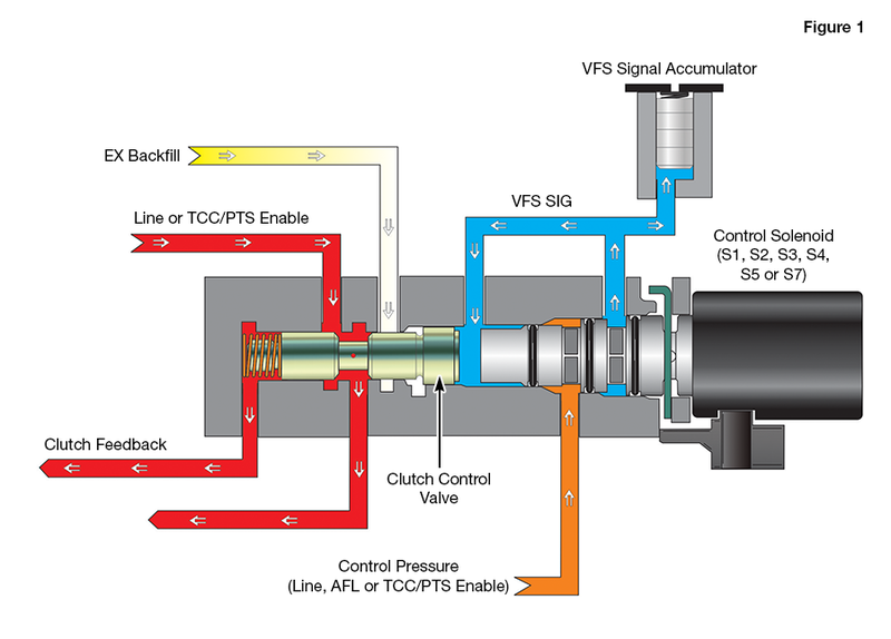
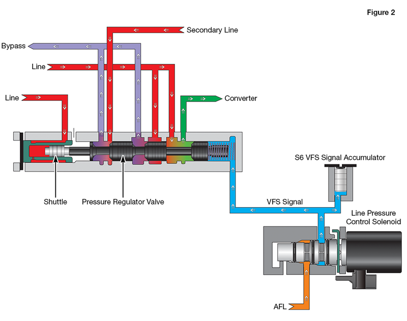
Before making that expensive decision, a look at the seven VFS solenoid circuits points to another location that is often the culprit and can be individually resolved. These solenoids are all low flow, as they are simply providing the flow and pressure to move a related clutch control valve, or in one instance, the pressure regulator valve. These related control valves are doing the heavy lifting of controlling the actual flow to apply the clutches, converter clutch and control main line and secondary line pressures (Figures 1 & 2). One thing in common on all of these VFS circuits is the addition of a small signal accumulator piston. These little pistons are used to help control the shift feel of the specific circuit by dampening any pressure and flow instabilities that could affect the related control valve. As a result, these very active valves tend to wear the cast aluminum bore that they live within. Because these are low flow solenoids, any loss of the signal fluid through this wear path has a significant impact on the related control valves and shifts.
| Figure 1 – Typical Clutch Control Solenoid Circuit |
|---|
 |
| Figure 2 – Line Pressure Control Solenoid Circuit |
|---|
 |
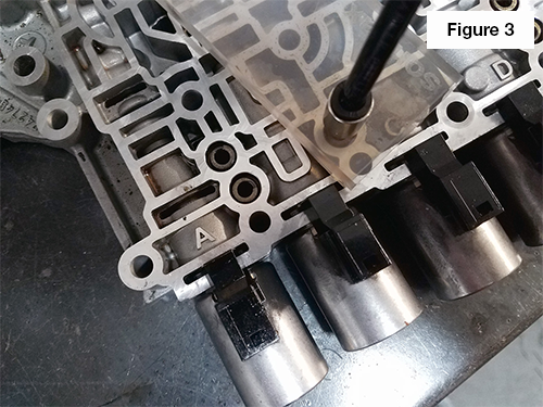
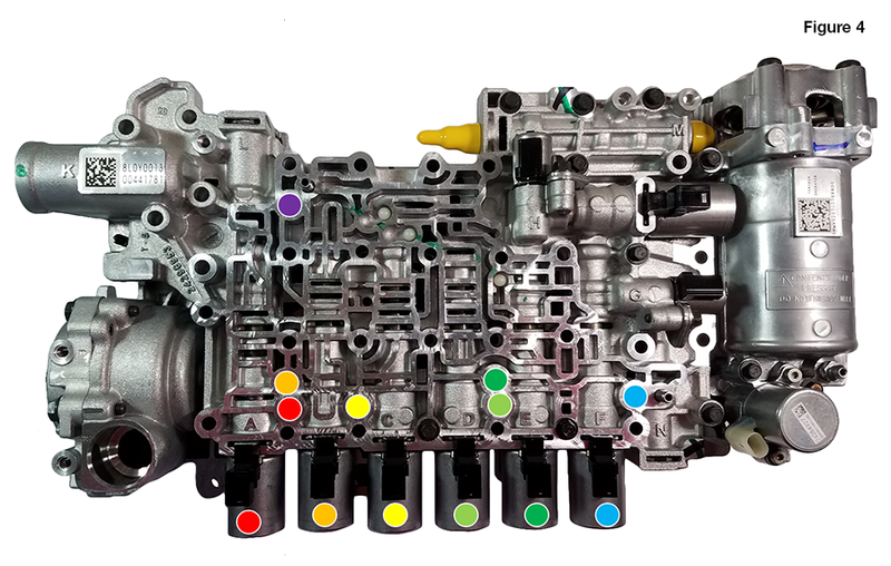
These signal accumulator pistons can be easily vacuum tested for wear (Figure 3). It is best to test these with the spring still in the piston, and place the test port opening in the center of the spring. Experience has shown that the S3 and S4 locations are generally the worst. A consideration when addressing any potential solution for this wear is replacement material, and ensuring a like (aluminum) material is used to mitigate any increased clearance between bore and piston at operating temperature due to different thermal expansion rates. The color-coded valve body image (Figure 4) and chart (Figure 5) identify which solenoid and signal accumulator should be considered for various shift or drivability complaints.
| Figure 3 – Vacuum Testing Signal Accumulator Pistons |
|---|
 |
| Figure 4 – 8L45, 8L90 VFS Solenoid & Accumulator Piston Locations |
|---|
 |
| Figure 5 – VFS Solenoid & Signal Accumulator Piston Chart |
|---|
| NL means increasing solenoid current increases solenoid output pressure and fluid flow. NH means increasing solenoid current decreases solenoid output pressure and fluid flow. |
| VFS Solenoid | TCC | 2-3-4-6-8 | 1-3-5-6-7 | 4-5-6-7-8-Reverse | 1-2-7-8- Reverse | 1-2-3-4-5-Reverse | Line Pressure |
| Current Control | NL | NH | NL | NH | NH | NL | NH |
| Signal Accumulator Piston | S7 | S4 | S3 | S5 | S1 | S2 | S6 |
| Pressure Controlled (Circuit) | High (TCC/PTS Enable) | High (Line) | High (Line) | Low (AFL) | Low (AFL) | High (Line) | Low (AFL) |
| Related Complaints | Converter Apply/Release Complaints; Burnt Converter | 2nd, 3rd, 4th, 6th & 8th Gear | 1st, 3rd, 5th, 6th & 7th Gear | 4th, 5th, 6th, 7th & 8th Gear; Reverse | 1st, 2nd, 7th & 8th Gear; Reverse | 1st, 2nd, 3rd, 4th & 5th Gear; Reverse | Low Line Pressure; Slipping & Burnt Clutches; Various Shift Complaints |
Sometimes attention to the smallest of items can save you big dollars. If excess wear is detected in the signal accumulator piston bores, you can restore hydraulic integrity with the improved Sonnax piston and spring. Each piston features hardcoat anodizing and annular grooves to greatly enhance long-term durability and keep the comebacks away.
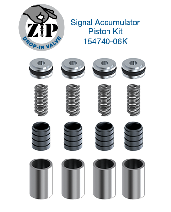 |  |
- Drop-in Zip Valve ™: Signal accumulator piston kit 154740-06K includes all the components you need to quickly and easily recondition up to four bores, no reaming required.
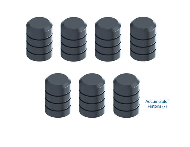
- Reaming Required: Oversized signal accumulator piston kit 154740-01K includes a complete set of seven pistons and is used with tool kit 154740-TL.
Maura Stafford is Sonnax vice president of transmission products. She is a member of the Sonnax TASC Force (Technical Automotive Specialties Committee), a group of recognized industry technical specialists, transmission rebuilders and Sonnax Transmission Company technicians.
Learn More
July 27, 2023
Tips for Tackling 8L45, 8L90 Shift Repairs with Sonnax Signal Accumulator Pistons
Caleb Perham
Related Units
Related Parts
Required
Recommended
8L45 • 8L90
Oversized Signal Accumulator Piston Kit 154740-01K
-
Helps cure:
- Poor shift quality
- Low line pressure
- No converter apply
- Hydraulic-related converter codes
- Burnt clutches
- Soft shifts

While Sonnax makes every effort to ensure the accuracy of technical articles at time of publication, we assume no liability for inaccuracies or for information which may become outdated or obsolete over time.