Upgrading the Honda Impeller-to-Stator Bearing
Ed Lee
Torque converter rebuilders have been reporting Honda bearing failures in increasing numbers. The bearing failures have been from different locations within the converters and have been reported in most Honda and Acura models. The most common of the failures has been the bearing located between the impeller and stator in the larger diameter converters. In all converters, the bearing in this location carries most of the thrust load when the vehicle is accelerating, and it is typically the first bearing to fail. Because the larger diameter converters are used in the larger, higher torque V6 applications, the thrust loads on this bearing are even greater.
 |
 |
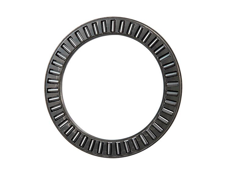
A root cause analysis completed on the failed bearings found that, although the thrust load on the bearings was a factor, it was not the primary cause of the bearing failures. The OE Honda bearing for this application is an open-faced bearing (HO-N-6) that uses the thrust surface of the flanged impeller hub as one of its bearing races. The impeller hub in Figure 1 is typical of a failed unit.
A close inspection of the impeller hub in the failed converter yielded several clues about the failure. The obvious discoloration caused by overheating was the first clue. The potato chip wear pattern was a second clue, and the wear pattern that extended the entire length of the circumference was a third clue. Since the Honda converters are well known for their overheating issues, it would have been easy to jump to the conclusion that the converter overheating took the temper out of the bearing surface of the impeller hub and caused the bearing failure. Converters which have overheated enough to turn blue have been hot enough to alter the temper of the metal. A check of the hardness of this surface seemed to back up this assumption. The normal hardness of a bearing race should be in the 58–60 Rockwell range, and the bearing surface of this impeller hub was as low as 50 Rockwell at one point.
While the overheating issue remained a good candidate for causing the temper loss, it was not the only possibility. The hub in this unit was not the original, but a replacement. Now the question became: did the converter overheat enough to affect the replacement hub's hardness or was the temper taken out of the replacement hub's bearing surface during the installation welding process? Testing the hardness of the impeller hub's bearing surface before and after the weld process would be necessary to answer this question.
 |
 |
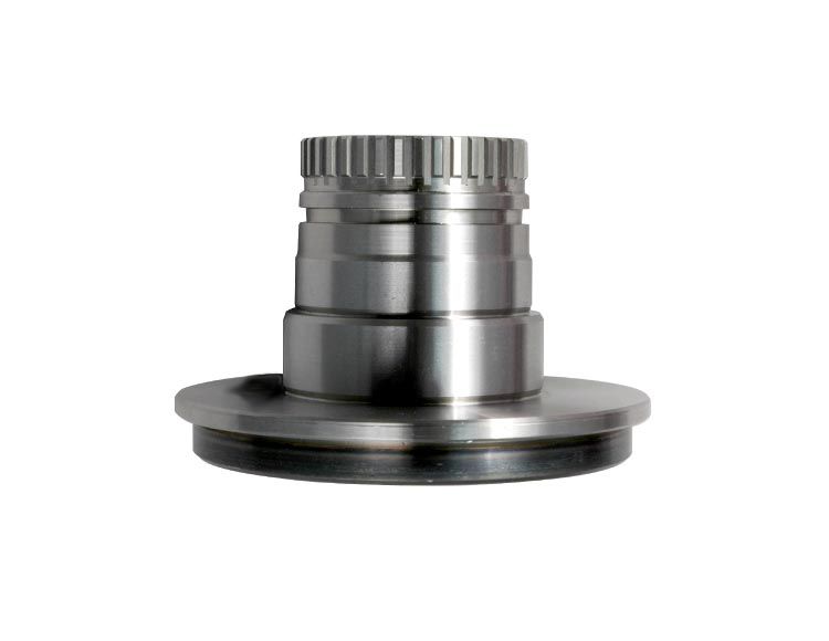
The bearing surface of a virgin replacement impeller hub (HO-90-4G) was tested and fell within the 58–60 Rockwell range. The impeller hub was then welded into the impeller and the hardness was retested. Starting at the beginning of the weld and continuing about 75% of the duration of the weld, the hardness remained in the 58–60 Rockwell range. The hardness measured near the last 25% of the weld was a different story. In this area, the hardness varied by 10 Rockwell and at one point dipped as low as 50 Rockwell. The results of the second hardness test led to several conclusions. One was that the wear at the entire circumference of the bearing surface in Figure 1 was probably caused by the loss of temper during the weld process, and that the potato chip distortion also was caused by the same heat. A second conclusion was that Honda had recognized this issue and addressed it by using a two-headed welder to install all of its impeller hubs (see Figure 2).
The third conclusion was that it was either time to invest in a two-headed welder or source a suitable enclosed bearing to replace the Honda OE bearing. Since two-headed welders are very expensive, the enclosed bearing seemed to be the better choice.

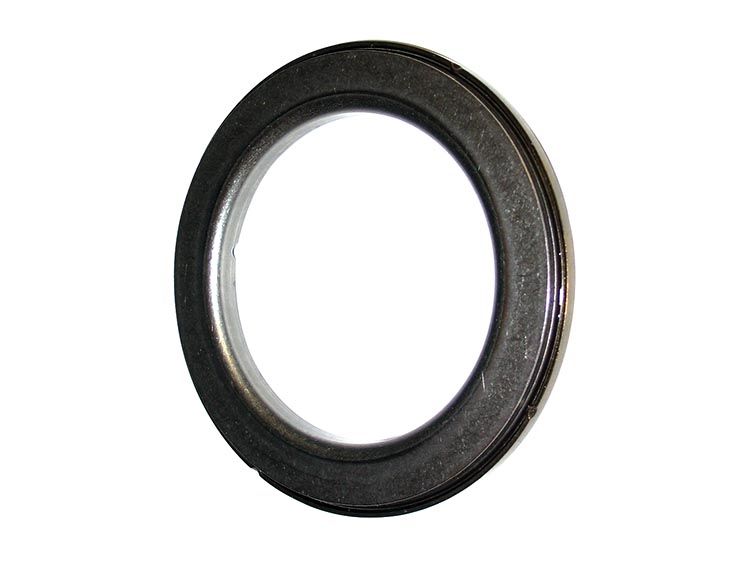
The bearing (JA-N-13) found between the stator and impeller in most RE5R05A converters is a good replacement bearing (Figure 3). It is very robust, and dimensionally it is ideal for the application. It is .035" larger in diameter than the cavity where the OE bearing and wear plate live, so a minimal clean up of the bore is all that is necessary to fit the bearing into the stator (Figure 4). Continuing the machining process to the bottom of the bore will provide plenty of lube oil for good bearing life. The finished product will look like Figure 5.
Another plus of using this bearing is that it is about .040" thicker than the combined thickness of the OE bearing and wear plate. This extra thickness allows you to either clean up the wear on the OE impeller hub or remove the potato chip distortion of the replacement hub caused by the welding process.
Ed Lee is a Sonnax Technical Specialist who writes on issues of interest to torque converter rebuilders. Sonnax supports the Torque Converter Rebuilders Association.
Related Parts
Required
Recommended
B7TA, B7VA, B7YA
Impeller Hub HO-90-4G
- Tooth Count: 38 External
- Pump Drive Style: Spline
- Hub Mount: Flanged
- Material: Hardened Steel
- Assembled Height: 1.811"
- Journal Dia.: 1.574"
- Flange Outer Dia.: 3.100"
- Height: 2.100"
Required
Recommended
B7TA, B7VA, B7YA
Thrust Bearing HO-N-6
- Bearing Style: Open
- Material: Hardened Steel
- Inner Dia.: 2.165"
- Thickness: 0.118"
- Outer Dia.: 2.953"
Required
Recommended
B7TA, B7VA, B7YA, JF010E (RE0F09A), JF506E (with sensor ring), Powerglide, TH350, TH400 (258mm) Performance Converter, Powerglide, TH350, TH400 (265mm) Performance Converter, RE4R01A, RE5R05A, RE7R01A (JR710E)
Thrust Bearing JA-N-13
- Bearing Style: Enclosed
- Material: Hardened Steel
- Inner Dia.: 2.213"
- Thickness: 0.236"
- Outer Dia.: 3.228"
While Sonnax makes every effort to ensure the accuracy of technical articles at time of publication, we assume no liability for inaccuracies or for information which may become outdated or obsolete over time.


