February 22, 2016
Too Close For Comfort: Pinpointing 4L60-E Gear Train Assembly Problems
Steve Garrett
In Part 2 of this series we will be diving deeper into the workings of one of the automatic transmissions that we introduced in Part 1: the 4L60. Now that we know the history of how these units came to be, let’s look closer at what makes them work and the improvements that were made over time to make them work better.
We will start by discussing the first true automatic transmission: the hydraulic planetary automatic transmission. This type of automatic utilizes several planetary gear sets, bands, clutches and a hydraulic system to achieve the different gears. For this example we will use the well-known GM 4L60 (also known as the 700-R4 — the OEM changed the unit name in 1989). This transmission had seven positions on the gear selector: P, R, N, D, 3, 2, 1. These selections were:
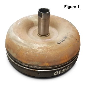
Before we dive into the power flow in each gear, it’s important to understand that the power must be transferred from the engine to the transmission. That is where the torque converter (Figure 1) comes into play. You can see a detailed diagram of every component in a 4L60 298mm torque converter here.
| Figure 1 –Assembled 4L60 Torque Converter |
|---|
 |
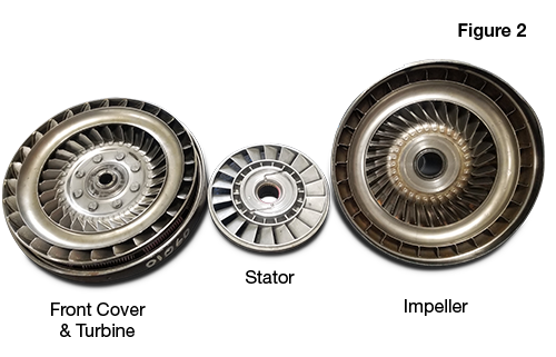
The clutch pedal on standards allows the engine to be momentarily disconnected from the transmission to allow the vehicle to travel forward in several gears, travel in Reverse and placed in Park. In the early days of automatics this is where the fluid coupling came into play. A fluid coupling is an oil-filled housing that includes two turbine halves. The cover assembly is attached to the flywheel and spins at the same RPM as the engine. The turbine assembly is splined to the cover, which propels the transmission fluid through the angled fins on the turbine towards the other turbine — the pump — which is splined to the input shaft (Figure 2).
| Figure 2 – 4L60 Torque Converter Turbine Components |
|---|
 |
An age-old comparison to show how this process works is to set up two desk fans facing each other and only turn one on. If they are close enough to each other, the air flow from the powered fan will propel the other fan to spin. Much like there isn’t a mechanical connection between the fans, there isn’t actually any mechanical link between the engine and transmission. Fluid couplings were phased out when torque converters were invented.
The difference between a fluid coupler and a torque converter is that a torque converter contains a stator inside the housing. The stator is a cylindrical, turbine-like piece that is installed between the turbine assembly and the converter pump assembly. Its job is to multiply torque by adding another redirection to the fluid path. The fluid now travels from the turbine assembly to the stator assembly, which redirects the oil and changes its direction of rotation to the same as the pump. This redirection increases the force of the oil that is driving the turbine therefore multiplying torque.
After the power is transferred from the engine through the torque converter, it is transferred by the turbine shaft that is pressed into the input housing. The input housing contains the Forward clutch housing, piston, clutch plates, clutch outer race, roller assembly, clutch cam and finally the input sun gear. This brings us to our first planetary set: the input planetary.
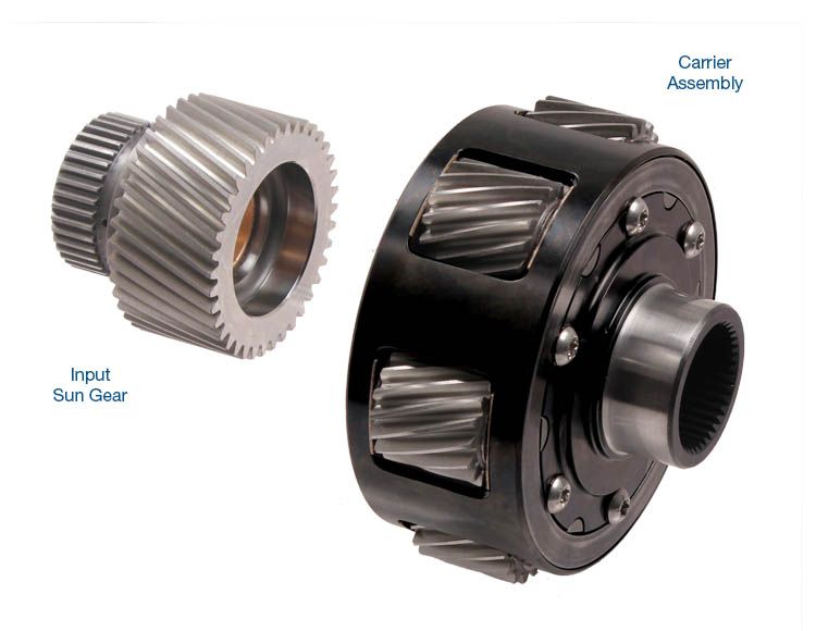
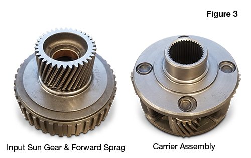
Planetary gears are named appropriately as they resemble a planetary system. They can be used to increase or decrease the twisting force or torque from the engine. The planetary consists of a center gear called a sun gear, surrounded by pinion gears, which are surrounded by an internal gear. For example, in GM’s 4L60, there are two planetaries: the input (or front) and the reaction (or rear) carrier (Figure 3).
| Figure 3 – 4L60 Input & Reaction Carrier Planetaries |
|---|
 |
Transmissions from other manufacturers will have different components and different methods of applying each gear, but the general idea is still the same: use the planetary gear set to provide the correct gear according to load and speed. Let’s take a look at the power flow with the 4L60 (700-R4).
First Gear requires more torque to get the vehicle moving from a standstill. This is accomplished by a process called reduction. In 1st Gear when Drive range is selected, the Forward clutches are applied holding the one-way Low and Reverse clutch, which prevents counterclockwise rotation of the reaction carrier because they are splined together. The reaction carrier is splined to the internal gear. Power is applied through the sun gear in a clockwise direction.
This makes the pinion gears of the input carrier orbit around the sun gear in a clockwise direction while individually rotating counter clockwise. Since the internal gear is restrained from rotating counterclockwise, the input carrier is forced to drive the output shaft which it is splined to. This results in a 3.06:1 torque multiplication and speed reduction. In other words, the input shaft will turn 3.06 times for every one rotation of the output shaft. Combine this ratio with the maximum converter torque multiplication of 2.0:1 and you have a 6.12:1 overall ratio.
When shifting into 2nd Gear, less torque and more speed is needed than 1st Gear. The Forward clutches are still applied, but the input internal gear and Low and Reverse clutch are released. The Reverse input drum is held by the 2-4 band, which is a circular band of metal with a friction surface bonded to it. Since the Reverse input drum is tanged to the sun shell, which is splined to the reaction sun gear, all three components will now be locked together. The input sun gear then drives the input carrier, output shaft and reaction internal gear. This forces the input carrier to transfer power to the reaction internal gear through the output shaft. Second gear ratio ends up being 1.44:1 because of the second reduction the reaction planetary provided.
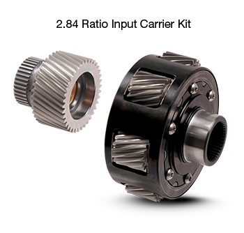
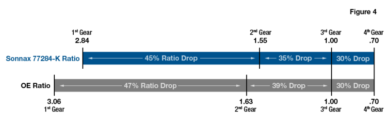
Damage to the band, input/output shafts, sprag, etc. can be lessened by properly cushioning the large ratio change on the 1-2 shift. Reducing the ratio change will improve overall launch in powerful applications, plus reduce stress on band and clutches on the shift by converting 1st Gear from 3.06 to 2.84. Sonnax input carrier kit 77284-K is a unique gear set that does exactly this. Figure 4 shows the OE torque multiplication factors and ratio changes with an OE reaction carrier vs. the Sonnax carrier. Learn more about cushioning the 1-2 shift ratio change and the benefits of the Sonnax 2.84 gear set in this article.
| Figure 4 – OE vs. Sonnax 4L60 Gear Ratios |
|---|
  |
In Third Gear the Forward clutches remain applied, the 2-4 band is released and the 3-4 clutches are applied. Power then flows through the input housing, forward clutches, input sprag and 3-4 clutches to the input sun gear. The input planetary carrier then drives the output shaft at 1:1 ratio, or direct drive as it is known. As the speed increases, less torque is required, hence the need for different ratios.
Fourth Gear, or Overdrive as it is known, is unique in that it is the only overdriven gear. By applying the 2-4 band, the Reverse input housing, input internal gear and reaction sun shell are held similar to 2nd Gear. The difference between 2nd and 4th Gear is that in 4th the 3-4 clutches are applied, which drives the carrier, which in turn drives the internal gear driving the output shaft at a ratio of .70:1. Overdrive still maintains vehicle speed, but improves fuel economy by lowering the RPM of the engine.
Placing the transmission in Reverse activates the Reverse input clutches inside the Reverse input housing, which is tanged to the input housing. The reaction carrier is prevented from rotating clockwise by the Low and Reverse clutches. The power now travels from the converter through the input housing, to the Reverse input housing, to the reaction sun shell, to the reaction sun gear. Since the carrier is being held, the sun gear will drive the reaction carrier pinons counterclockwise on their pins, which drives the reaction internal gear and output shaft counterclockwise at a ratio of 2.30:1.
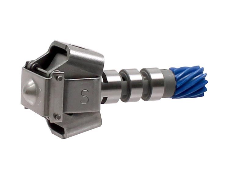
Shift timing in early planetary transmissions is controlled strictly by hydraulic pressure that is supplied by a mechanical governor (Figure 5) that is driven by the output shaft.
| Figure 5 – 4L60 Governor |
|---|
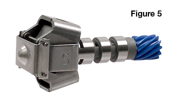 |
The governor is supplied with a constant pressure from the oil pump. When the governor spins at slow speeds, centrifugal force acts on the larger and heavier primary weights first, pushing them outward, which moves the internal valve inside the governor closing the exhaust port and increases the governor pressure. Once the vehicle reaches a speed that forces the primary weights all the way out, they become unable to affect shift timing, which is when the smaller secondary weights come into play. Because of their smaller weight, they are less affected by centrifugal force and provide the smaller adjustments at higher speeds.
Modern transmissions rely on electronic speed sensors and the vehicle’s throttle position sensor to provide the engine load information to the transmission control module (TCM).
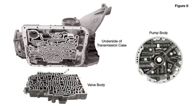
While the governor controls the timing of the shifts, the hydraulic system is responsible for applying the clutches and bands. The heart of the hydraulic system is the pump, which is keyed to the converter pump hub and turns when the engine is running. The pump in a 4L60 (700-R4) is a rotor-and-vein-style and provides the necessary line pressure to the hydraulic system to apply the bands and clutches.
The previously mentioned gear selector that allows the driver to select the desired range is connected to the manual valve inside the valve body. The manual valve directs the fluid path from the pump to the valves of the valve body. The valve body is a complex assembly of interconnected fluid paths, precision valves, checkballs and orifices (Figure 6).
| Figure 6 - 4L60 Valve Body & Pump |
|---|
 |
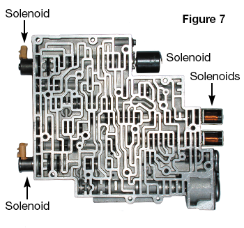
In older units, the valve body would utilize a valve for each specific gear change, called a shift valve. Each shift valve when stroked in the correct direction completes the fluid path necessary to activate the clutch pack(s) and/or band to achieve the appropriate gear. In modern transmissions such as the successor to the 4L60 — the 4L60-E (Figure 7) — gear changes are achieved electronically, instead of hydraulically, by using solenoids.
| Figure 7 – 4L60-E Valve Body with Solenoids |
|---|
 |
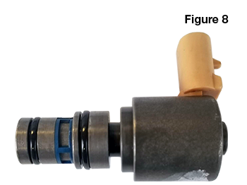
A solenoid (Figure 8) is an electromagnetic valve that can be opened or closed by applying voltage across the solenoid coil by the transmission control module.
| Figure 8 – 4L60-E Solenoid |
|---|
 |
The actual application of the clutch pack or band is accomplished by using pistons and servos. These are devices that convert hydraulic pressure into mechanical force to provide the clamping force necessary to hold the band or clutches without slippage. Stock and aftermarket servos come in different sizes to deliver different degrees of holding power. Learn more about 4L60-E servo options in this tech article.
While the main principles of the hydraulic planetary transmission have remained mostly unchanged since transmissions like the 4L60 (700-R4), improvements had to be made to increase fuel efficiency to meet the demands of tightening emissions. As covered in The Evolution of Automatic Transmissions Part 1: A Brief History, manufacturers accomplished this by adding additional gears. Using General Motors as an example, for the front-wheel-drive platforms they went from the 4-speed 4T40-E and 4T65-E to a 6-speed 6T70 in 2007 for V-6 applications and 6T30/40 in 2008. For the rear-wheel-drive platforms, they started upgrading the 4-speed 4L60-E to 6-speed 6L80 in 2006, then to the 8-speed 8L90 in 2014 and finally to the 10-speed 10L90 in 2017. Other manufacturers of course followed a similar path of progression of adding gears to improve vehicle efficiency.
Jason Larochelle is a Sonnax product support representative. He is a member of the Sonnax TASC Force (Technical Automotive Specialties Committee), a group of recognized industry technical specialists, transmission rebuilders and Sonnax technicians.
February 22, 2016
Steve Garrett
March 02, 2016
February 26, 2021
Gregg Nader
While Sonnax makes every effort to ensure the accuracy of technical articles at time of publication, we assume no liability for inaccuracies or for information which may become outdated or obsolete over time.