Breaking Down the Basics of Banded Solenoids
Eric Streed
We are all familiar with tolerances in one way or another when dealing with 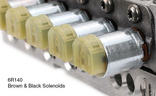 complex mechanical assemblies like automatic transmissions. One of the most common examples is a clutch pack when overhauling a unit. Friction discs often vary by a couple thousandths of an inch. If you’re building a five-pack clutch and all the frictions are oversized by +.002", then you have what’s called a “tolerance stack up” of +.010". A builder would typically compensate for this by changing a pressure/end plate to a different thickness to bring the clutch clearance into the correct window.
Solenoids are also affected by tolerance stack up. There are many components in a modern solenoid, all with their own individual manufacturing tolerances. For years, solenoid manufacturers have overcome this variability with an adjustment screw to dial in a specific output pressure for a given control current. What some manufacturers are now doing to address this issue is to use multiple tolerance bands and specialized programming to widen the window of acceptability.
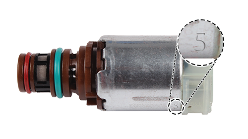
Each individual solenoid is tested and marked with a band number (Figure 1) based on its performance. The most widely produced of these banded solenoids are those used in Ford 6F and 6R applications. Digging deeper into how these operate, let’s discuss how the solenoids’ bands are determined.
| Figure 1 – 6R140 Solenoid Band Number |
|---|
 |
The solenoids are driven from minimum to maximum current (i.e., 0–1 amps), and the output pressures are monitored and recorded. Which bandwidth zone the output pressure passes through determines the band of the solenoid. We selected 31 psi as an arbitrary pressure to review a 6R140/6R80 brown solenoid’s bandwidth (Figure 2). Notice there are five bandwidth zones of approximately 20mA per band. Looking specifically at the brown band 3 solenoid in Figure 2, the solenoid amperage is 492mA, which falls into the band 3 zone of 475–495mA.
| Figure 2 – 6R80, 6R100, 6R140 NL Solenoid Bandwidth at 31 psi |
|---|
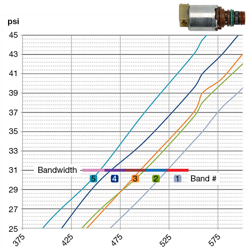 |
Having five bands for each solenoid allows for approximately a window of 8 psi at a specified current for both normally low and normally high variants.
The major caveat here is that the TCM needs to be told ahead of time which bands are in each location, as a single baseline program cannot compensate for such a wide window of solenoid operation. This is where the unique band numbers come into play.
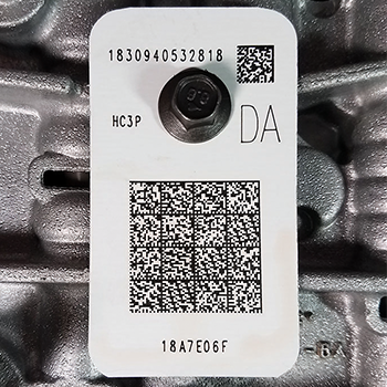
One example of this is the Ford 6R140 transmission, which uses a 13-digit solenoid body strategy along with an eight-digit solenoid body identification (Figure 3). Both codes can be found on a tag on the valve body as well as on the side of the transmission case. Programming these codes into the vehicle’s TCM tells the vehicle which band solenoid is in each solenoid location.
| Figure 3 – 6R140 Solenoid Body Strategy & Solenoid Body Identification |
|---|
 |
Which band has the highest pressure?
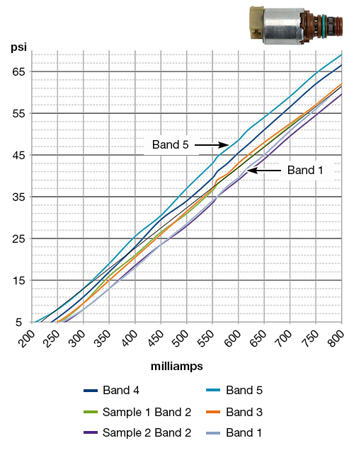
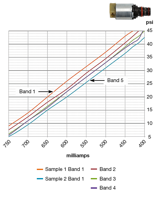
For the brown (NL) solenoid, band 5 has the highest pressure output (Figure 4). For the black (NH) solenoid, band 1 is the highest pressure (Figure 5). People often state, “I changed from a band 2 to a band 3, and there is no difference.” This is possible. Looking at Figure 2, you will see the “high pressure” band 2 pretty much matches the “low pressure” band 3. It depends on where the solenoid falls in the band zone.
| Figure 4 – 6R80, 6R100, 6R140 NL Solenoid Pressure Output |
|---|
 |
| Figure 5 – 6R80, 6R100, 6R140 NH Solenoid Pressure Output |
|---|
 |
We are assuming the GM 8L90 with Part Unique Number (PUN) valve body, which is programmed to transmission, will follow a similar pattern, but more testing needs to be done to confirm this. Controlling the amperage was the most critical factor we noticed early on trying to figure out these bands.
All valve body test machines (as of spring 2022 when this article was written) drive the solenoids by controlling the duty cycle. When the duty cycle is changed, it affects the output pressure of the solenoid. The problem with a duty cycle-controlled system is that as soon as the solenoid coil temperature changes, the coil resistance changes. This, in turn, changes the amperage. As the temperature changes in a solenoid, you will get different output pressure for a given steady current.
It’s a constantly moving target, just like a dog trying to catch its own tail.
The only way to remedy this is to have a controller that constantly monitors amperage and adjusts duty cycle accordingly. It’s similar to how an oxygen sensor monitors the air/fuel ratio in an engine and changes command to the fuel injector several times per second. Often, OE and aftermarket solenoids will vary in coil resistance. This is okay as long as the coil is within tolerance (e.g., if you replace a 5 Ohm solenoid with a 6 Ohm solenoid). Amperage control in TCM will easily account for this, but they would test drastically different when tested on a conventional valve body test machine.
Related Units
While Sonnax makes every effort to ensure the accuracy of technical articles at time of publication, we assume no liability for inaccuracies or for information which may become outdated or obsolete over time.