CVT Success: In-Vehicle Isolation of Common Problems
Bob Warnke
All transmission models have unique problems that are common to that model; Jatco CVT units are no exception. Technicians are facing an uphill battle when it comes to diagnosing and repairing CVTs if they don't have the right information on hand. Knowing what the common issues are and understanding the options available to isolate and fix problems are the keys to CVT success.
First, Do No Harm
Without the right information, we end up making assumptions — often incorrect ones. Generally, when unfamiliar with a transmission, we start by searching bulletins and websites for service clues. Sometimes we read a tip and assume that the information matches our complaint. If we are action-oriented and short on time, we might react too quickly and assume that pulling out the unit for repair is best. But too often, assumption takes the long path — to the wrong conclusion.
The following are examples of “runaway” assumptions:
- After pulling the pan for routine maintenance service on a unit with 40,000 miles, the technician finds the magnets heavily loaded when compared to a typical automatic. It looks like the unit is well on its way to failing.
- After cleaning the magnets and refilling the unit with the correct CVT fluid, the car is test driven around the block. It works well and is ready for delivery.
- Two days after picking up the car, the owner comes back claiming the vehicle has excess noise and seems to slip. Because of the material previously found on the magnets, the decision is made to pull the transmission.
Hold on, action-oriented enthusiast. Not so fast! If you want to be CVT-successful, you’ve got to know why these assumptions are incorrect. Once you have that information, you can get down to the business of learning some of the common CVT problems and their causes, all without removing the unit from the vehicle.
The first false assumption has to do with the magnets. A certain amount of magnetic fuzz is normal in a CVT inspected with 40 to 50 thousand miles. The push-belt links create fretting where they contact the sheave/pulley surface, most of which is generated during break-in. But in noting this material is normal, consider that much of that ferrous fuzz has been circulating throughout the valve body. It has embedded into the solenoids and stuck onto the speed sensors — all of which are electromagnets — while also scrubbing away at the aluminum valve bores. This means that the fuzz is indeed normal, but so is low-mileage valve bore wear.
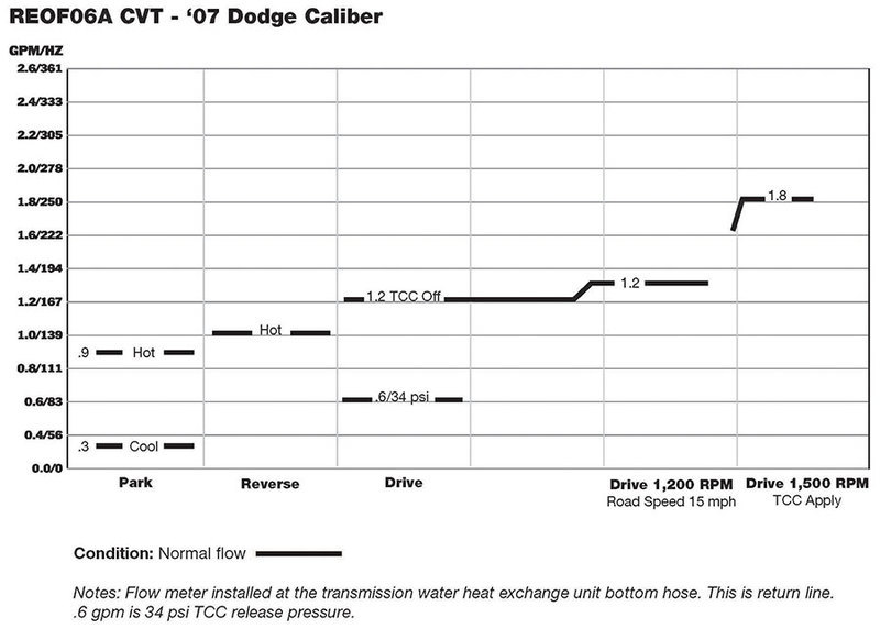
The second incorrect assumption was that test driving the vehicle around the block after fluid exchange was sufficient. These units use a thermal element in the water-to-oil (WTO) cooler. The fluid must reach approximately 150°F for the element to open and flow oil to the cooler. Once it opens, air is purged, leaving the sump level low. Low fluid causes chain slip and noise on acceleration. Driving it in this low-fluid condition will end up damaging the unit and requiring a tow-in.
The third erroneous assumption was that the transmission needs to be pulled out. As we’ve just seen, committing to pulling the unit before verifying correct fluid level would be a mistake. There is no dipstick, and guessing what drained from the pan is not sufficient. You can buy a dipstick from Chrysler or aftermarket sources, or you can make your own. The transmission fill tube has an internal stop at the bottom. You can make a dipstick and place marks in 10mm increments starting at the bottom and moving upward. At 75°F, minimum/maximum fluid level must be 26mm to 38mm. At 180° F, minimum/maximum fluid level must be 38mm to 46mm.
Known-Good Values
We’ve just identified some non-issues, but what about when we run into an actual problem? Let’s look at some information that will help isolate those problems once they are presented in the shop. The following charts and diagrams (Figures 1-6) show the pressure specifications, tap locations and flow testing information you’ll need for diagnosis.
| Figure 1: Maximum Pressure of the Four Types of Circuits in JATCO CVTs | |||
|---|---|---|---|
| Primary & Secondary Pulley* | Forward & Reverse Clutch | TCC Apply | Lube & Cooler |
| 870 psi (5,998 kPa) | 218 psi (1,503 kPa) | 138 psi (951 kPa) | 60 psi (413 kPa) |
| Figure 2: Typical Pressures Under Specific Shift Conditions | ||||||||||
|---|---|---|---|---|---|---|---|---|---|---|
| Park Initial Start | Park Idle Hot | Reverse | Reverse Stall | Neutral | Drive Idle Hot | Drive Acceleration | Drive Acceleration to 1,500 RPM | Drive TCC Apply at 1,500 RPM | Drive Stall | |
| Primary & Secondary Pulley Pressure* | 20, 60–325 psi (137, 413–2,240 kPa) | 173 psi (1,192 kPa) | 270 psi (1,861 kPa) | 125 psi (861 kPa) | 125–290 psi (861–1,999 kPa) | Drop to 180, then climb to 285 under acceleration (1,241 then 1,965 kPa) | 425 psi (2,930 kPa) | |||
| Line Pressure | About 140 psi (965 kPa) | 130–145 psi (896–999 kPa) | 850 psi (5,860 kPa) | 130–150 psi (896–1,034 kPa) | 150–240 psi (1,034–1,654 kPa) | 850 psi (5,860 kPa) | ||||
* The primary pulley pressure tap may not be accessible on all cases. Primary pressure should follow secondary pressure.
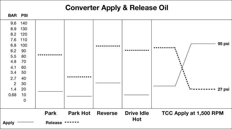
| Figure 3: Typical TCC Pressure |
|---|
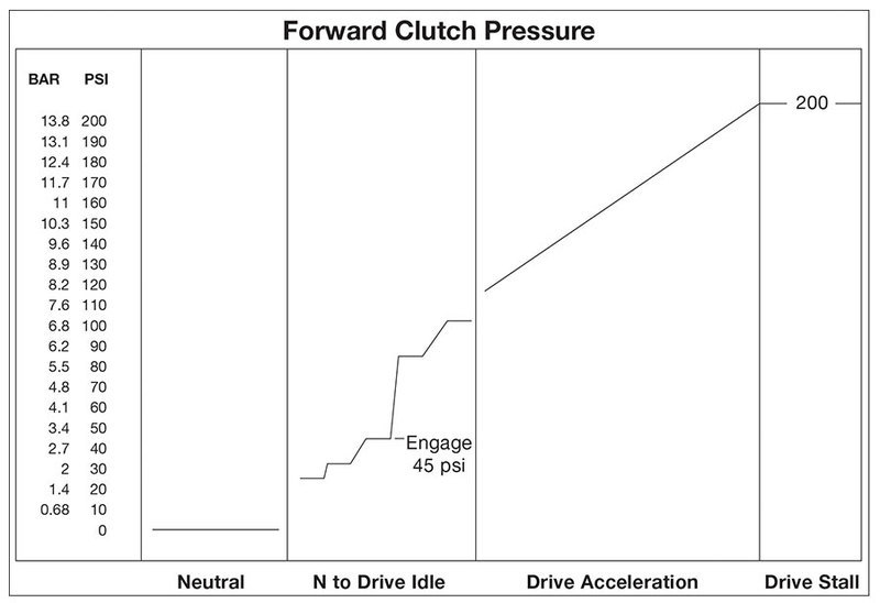
| Figure 4: Typical Forward Clutch Pressure |
|---|
| Figure 5: Flow Testing |
|---|
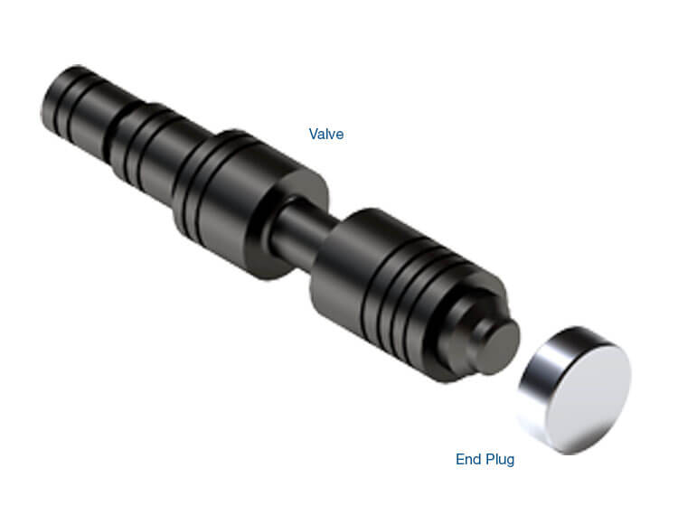
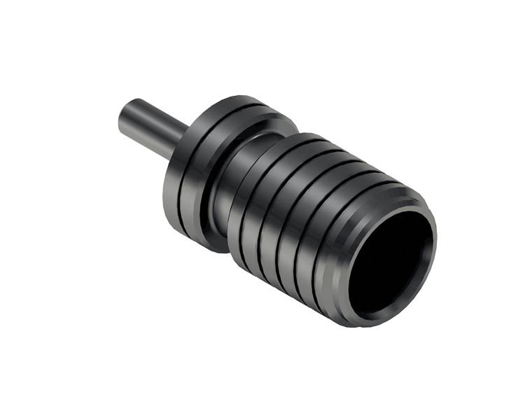
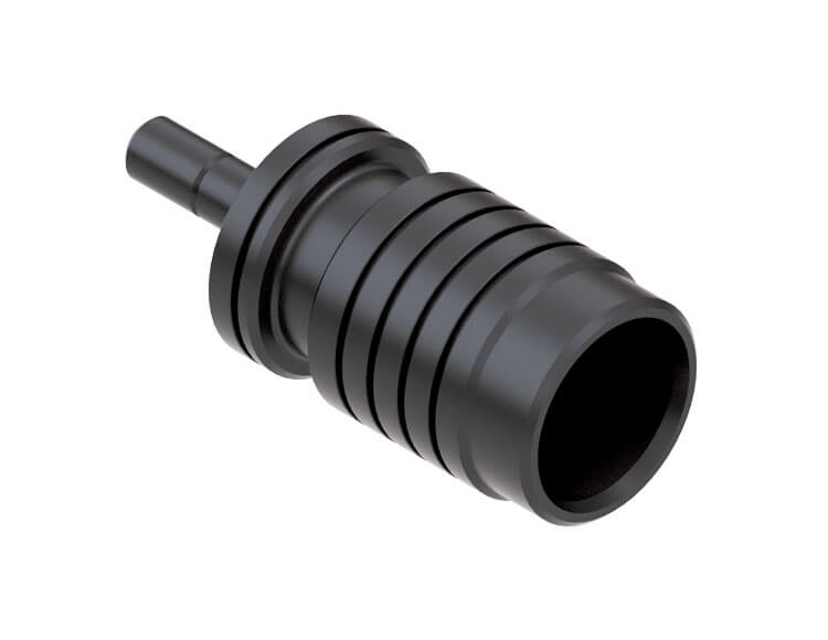
As you can see, there are some very high pressures here compared to regular automatics. For pressure testing, use a gauge with a minimum of 1,000 psi (7,000 kPa). A typical JATCO port adapter is required. If you don’t have one, make one by pre-drilling a center hole into a case plug, then brazing to a 1/8" pipe.
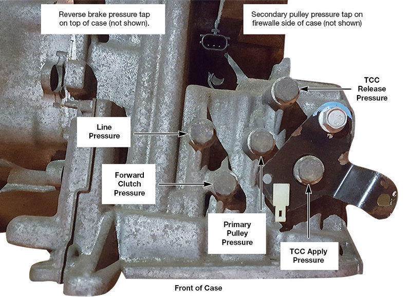
It’s easy to identify the pressure tap locations (Figure 6). Most of the taps and the fill plug face the front, toward the radiator and just below the input speed sensor. They form a four-point circle, with the primary pulley pressure tap in the middle. The Reverse brake tap is near the shift shaft on top and the secondary pulley tap is on the firewall side. Note: this configuration is specific to JF011E; tap locations differ on other CVT units. Consult available reference material for tap locations on other models.
| Figure 6: Pressure Tap Locations |
|---|
Isolating Common Problems
Let’s take a look at how we can use this information to isolate some common CVT problems. Remember that, because of the high pressures involved, it is suggested you hang the gauge outside the vehicle rather than inside.
In your quest to isolate these concerns, be aware that the converter clutch does not have a ramped apply. It locks dependent on engine RPM of about 1,500 on acceleration. The TCC does not unlock on deceleration until about 10 mph. In contrast, a typical automatic usually applies after a 1-2/2-3 shift and has controlled slip, which is required in those units for drivability and fuel efficiency.
The following represent the most common complaints on CVT units and areas to investigate:
- Chatter, noise or judder on acceleration
- Check line pressure, TCC release, Forward clutch and primary/secondary pulley pressure, as well as bearings.
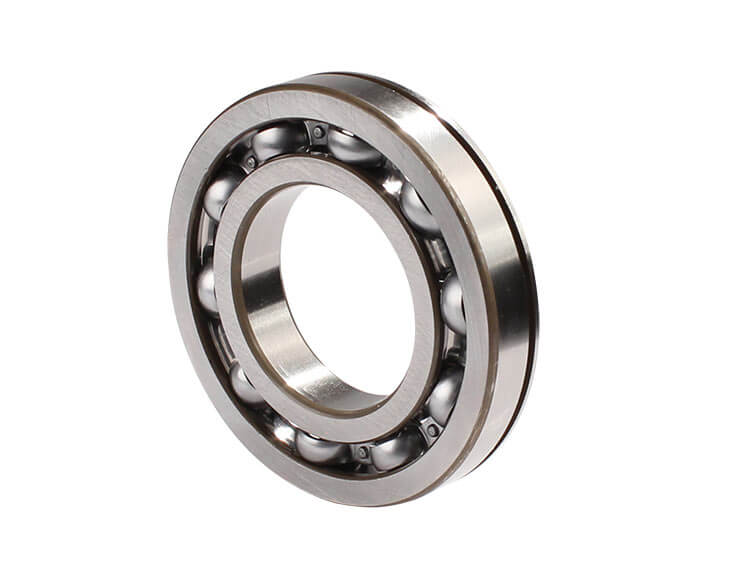
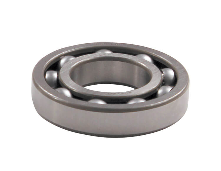
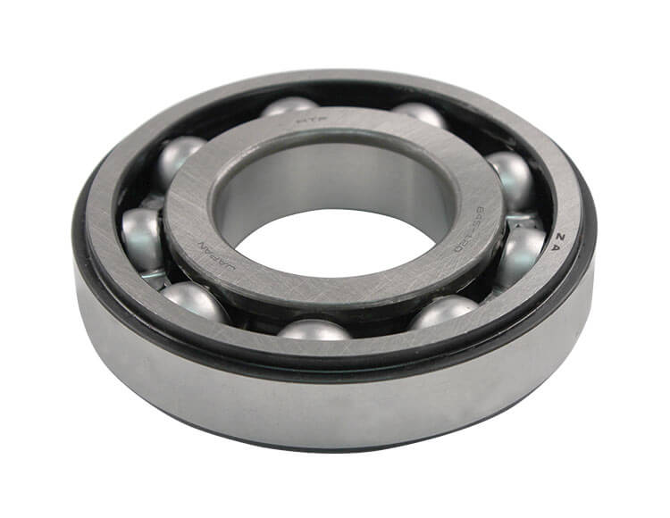
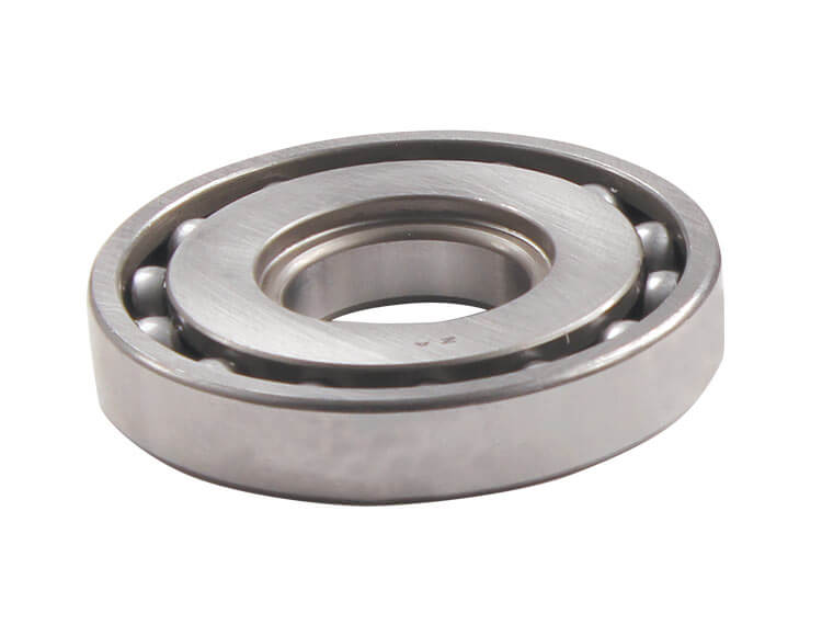
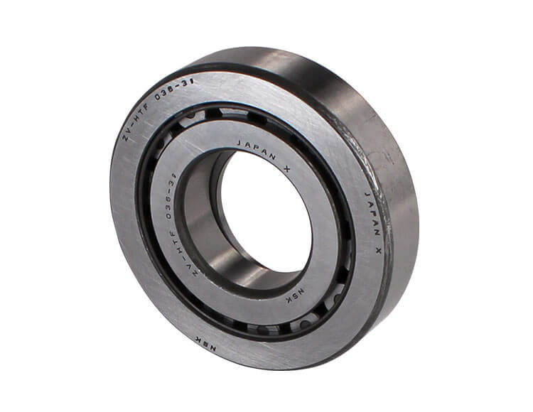
- Bearing failure is widespread. Usually with bearing failure, fluid level and pressures will be okay, but a whining noise will be evident on acceleration. To determine which bearing is making noise, drive at a constant speed (where the noise is strongest) and shift manually to a lower ratio — this makes engine speed increase. If the noise goes up with engine speed, the primary pulley bearing has failed. If the noise stays constant with RPM increase, the secondary or final drive bearing is the culprit. Sometimes, bearing noise can be accompanied by low secondary pulley pressure, because if that bearing is damaged, the shaft can run out-of-line and damage the pulley’s input seal. Replacement bearings are readily available in the aftermarket.
- RPM surge/stumble at idle, stall on engagement
- Check forward clutch pressure. Check cooler flow and/or TCC apply/release pressure.
- No TCC apply or RPM change at 1,500 RPM
- Check TCC apply and release pressure.
- Hydraulic noise at idle
- Check TCC release pressure.
When encountering low pressure, focus your inspection on the valve body. For each pressure circuit that is out of specification, vacuum test the associated bore. For instance, if you have low line pressure, you would move to vacuum test the primary pressure regulator valve/bore. If you have low primary pulley pressure, vacuum test the primary pulley control valve/bore, etc. If all pressures are low, suspect the pump flow control valve. In fact, this valve notoriously wears out on most units; it would be smart to replace it with an oversized version on every repair to prevent possible warranty comebacks. Failing flow control valves also will often cause codes to set such as ratio, pressure sensor and/or solenoid “A” or “B” codes.
As you can see, it is possible to use available information and test equipment to diagnose many CVT problems without removing the transmission. When armed with solid service information, an understanding of common problems and how to identify their causes, CVTs can be a good source of pain-free revenue for any transmission shop.
Bob Warnke is Sonnax vice president of technical development and a member of the TASC Force (Technical Automotive Specialties Committee), a group of recognized industry technical specialists, transmission rebuilders and Sonnax Industries Inc. technicians.
Related Units
Related Parts
Required
Recommended
Required
Recommended
JF010E (RE0F09A/RE0F09B) • JF011E (RE0F10A)
Oversized TCC Limit & Lube Valve Kit 113741-04K
Also fits Mitsubishi F1CJA.
-
Helps cure:
- Engine stall on engagement
- No lockup
- Increased RPM during acceleration
- Ratio codes
- Poor performance
- Overheated fluid
- Poor fuel economy
- Poor lube oil control
Required
Recommended
JF010E (RE0F09A/RE0F09B)
Oversized Pump Flow Control Valve 113741-07
Measure OE valve and spring cage first to ensure compatibility. Incorrect usage can create flow issues and early pulley damage.
-
Helps cure:
- Delayed engagement
- Push belt slippage
Required
Recommended
JF010E (RE0F09A/RE0F09B) • JF011E (RE0F10A)
Oversized Primary Pressure Regulator Valve Kit 113741-09K
Also fits Mitsubishi F1CJA.
-
Helps cure:
- Chatter on acceleration
- Damaged valve body casting
- Slips in Forward & Reverse
- Pulley breakage
- High line pressure
- Low line pressure
Required
Recommended
Required
Recommended
JF011E (RE0F10A)
Oversized Torque Converter Pressure Regulator Valve Kit 113741-13K
For JF010E units, use Sonnax kit 113741-15K. Also fits Mitsubishi F1CJA.
-
Helps cure:
- Converter shudder & TCC slip
- TCC apply & release concerns
- TCC codes
- Overheating
- Erratic TCC apply pressure
- Lube failures
Required
Recommended
JF010E (RE0F09A/RE0F09B)
Oversized Torque Converter Regulator Valve Kit 113741-15K
-
Helps cure:
- TCC slip codes
- TCC apply & release concerns
- Overheating
- Lube failures
Required
Recommended
JF010E (RE0F09A/RE0F09B)
Oversized Secondary Pulley Control Valve Kit 113741-17K
-
Helps cure:
- RPM surge on acceleration
- Chatter on acceleration
- Push belt slippage & pulley fracture
Required
Recommended
JF011E (RE0F10A)
Oversized Secondary Pulley Control Valve Kit 113741-19K
Also fits Mitsubishi F1CJA.
-
Helps cure:
- RPM surge or chatter on acceleration
- Push belt slippage & pulley fracture
Required
Recommended
JF011E (RE0F10A) • JF015E (RE0F11A) • JF016E (RE0F10D) • JF017E (RE0F10E) • JF019E (RE0F10J)
Oversized Pump Flow Control Valve 33510N-01
Fits '07-later. Also fits Mitsubishi F1CJA and F1CJB.
-
Helps cure:
- Push belt slippage
- Delayed engagement
- Low pump volume
Required
Recommended
Required
Recommended
JF015E (RE0F11A)
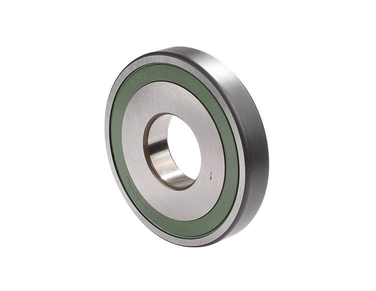
Secondary Pulley Front Bearing 323264-A
Also fits Mitsubishi F1CJB.
-
Helps cure:
- Bearing noise
- Bearing failure
- Push belt slippage
Required
Recommended
JF015E (RE0F11A)
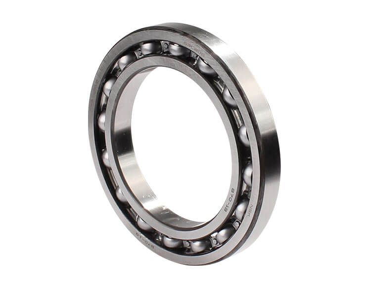
Primary Pulley Front Bearing 323235-C
Fits units paired to engines 1.6L or over only. Also fits Mitsubishi F1CJB.
-
Helps cure:
- Bearing noise
- Bearing failure
- Push belt slippage
Required
Recommended
JF015E (RE0F11A)
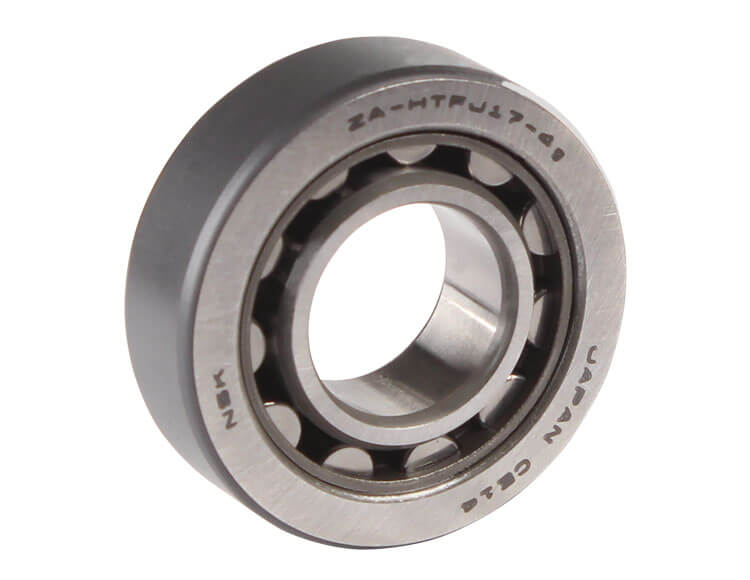
Secondary Pulley Rear Bearing 323229-A
Also fits Mitsubishi F1CJB.
-
Helps cure:
- Bearing noise
- Bearing failure
- Push belt slippage
Required
Recommended
JF015E (RE0F11A)
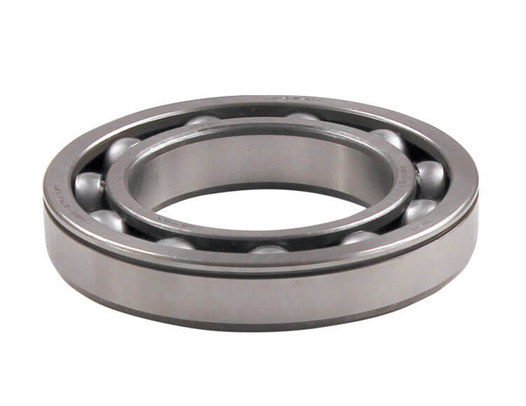
Input/Counter Drive Bearing 323232-A
Also fits Mitsubishi F1CJB
-
Helps cure:
- Bearing noise
- Bearing failure
Required
Recommended
JF011E (RE0F10A)
Primary Pulley Bearing 33236N
Fits torque converter side. Also fits Mitsubishi F1CJA.
-
Helps cure:
- Bearing noise
- Bearing failure
- Push belt slippage
Required
Recommended
JF011E (RE0F10A)
Primary Pulley Bearing 33235N
Fits cover side. Also fits Mitsubishi F1CJA.
-
Helps cure:
- Bearing noise
- Bearing failure
- Push belt slippage
Required
Recommended
JF010E (RE0F09A/RE0F09B)
Secondary Pulley Bearing 33229G
Fits cover side of RE0F09B.
-
Helps cure:
- Bearing noise
- Bearing failure
- Push belt slippage
Required
Recommended
JF010E (RE0F09A/RE0F09B)
Primary Pulley Bearing 33235G
Fits cover side.
-
Helps cure:
- Bearing noise
- Bearing failure
- Push belt slippage
Required
Recommended

JF010E (RE0F09A/RE0F09B)
Secondary Pulley Bearing 33228G
Fits torque converter side.
-
Helps cure:
- Bearing noise
- Bearing failure
- Push belt slippage
Required
Recommended
JF011E (RE0F10A)
Secondary Pulley Bearing 33228N
Fits torque converter side. Also fits Mitsubishi F1CJA.
-
Helps cure:
- Bearing noise
- Bearing failure
- Push belt slippage
Required
Recommended
JF016E (RE0F10D)
Primary Pulley Bearing 333264A
Fits front side.
-
Helps cure:
- Bearing noise
- Bearing failure
- Push belt slippage
Required
Recommended
JF016E (RE0F10D) • JF017E (RE0F10E) • JF019E (RE0F10J)
Primary Pulley Bearing 333235A
Fits rear side.
-
Helps cure:
- Bearing noise
- Bearing failure
- Push belt slippage
Required
Recommended
JF016E (RE0F10D)
Secondary Pulley Bearing 333229A
Fits rear side.
-
Helps cure:
- Bearing noise
- Bearing failure
- Push belt slippage
Required
Recommended
JF017E (RE0F10E) • JF019E (RE0F10J)
Primary Pulley Bearing 343264A
Fits front side.
-
Helps cure:
- Bearing noise
- Bearing failure
- Push belt slippage
Required
Recommended
JF017E (RE0F10E) • JF019E (RE0F10J)
Secondary Pulley Bearing 343229A
Fits rear side.
-
Helps cure:
- Bearing noise
- Bearing failure
- Push belt slippage
While Sonnax makes every effort to ensure the accuracy of technical articles at time of publication, we assume no liability for inaccuracies or for information which may become outdated or obsolete over time.