January 28, 2019
Hydraulics Fundamentals Part I: Main Pressure Regulator Valve Line-Ups
Zachary Richardson
Read Part I , Part II and Part III of the Hydraulics Fundamentals series.
As rebuilders, we often divide responsibility between sub-assemblies. Whether we build torque converters, valve bodies or transmissions, we place an expectation on the condition of the pump, gear train, valve body or converter that will be paired to our build. However, during diagnosis of any problem, we need to be able to trace and diagnose the entire affected circuit, not just the part of the circuit we are responsible for. Whether we build transmissions or converters, we must be familiar with the circuitry involved in each sub-assembly to ensure successful diagnosis. In modern vehicles, the converter clutch is very active and has become critical to drivability.
Most converter failures are related to the TC clutch and overheating conditions. To sort out these failures, we will divide the types and paths of various designs. Torque converter circuits include:
These definitions may vary between manufacturers.
Because of advancements in converter technology, fluid control has changed significantly over time. We start with the simple “fluid coupling,” defined as a stator-less, open converter. Early open (non-lockup) converters had one path: in/out. The inlet was charged by way of the pump stator support and fed by the line pressure regulator valve (Figures 1 & 2).
| Figure 1 – 4L80 Converter |
|---|
 |
| Figure 2 – Honda Main Regulator Valve |
|---|
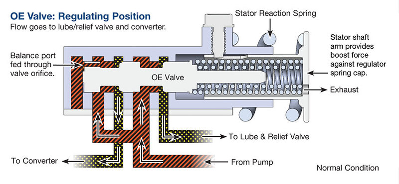 |
Charge pressure purges air from the converter and ensures fluid force between the impeller and turbine. Low converter pressure shows up as higher engine stall, low power, poor mileage, turbine blade damage and noise.
Before we proceed, we should understand that pressure and flow are not the same. Pressure is created by and ahead of a restriction as flow is forced to it. A converter assembly can be charged, or build up internal pressure, because of a designed restriction on the outlet. Flow exiting a converter will be sporadic if charge pressure is low. A poor charge with traditional ATF can starve the lube circuit for several miles after an initial start. Synthetic ATF improves flow in extreme cold, but the charge relies on proper valve and pump operation.
Pressure and the movement of fluid perform the work. Work creates heat, so circulation or flow is required to reduce heat. A non-lockup converter generates heat whenever the turbine RPM is not matched to the cover RPM. During deceleration, the wheels drive the turbine shaft faster than engine RPM, which also generates heat. Coupling speed (lockup in a TCC) is when the cover of the converter is turning the same speed as the turbine shaft.
The two-path lockup converter has a release oil circuit that flows through the center of the turbine shaft and exits the shaft between the TCC piston and cover. This pressure releases the piston and friction material from contact with the cover. The second path is apply pressure: the clamping force loading the piston onto the cover. As the release oil is exhausted, apply pressure is increased.
Two-path clutch control typically requires three to four valves to regulate the slip rate and turbine shaft RPM. The main regulator valve has a circuit leading to the converter. In the circuit is a TC control valve, which acts as the gateway for apply and release oil. Once the control valve is stroked by TC solenoid output, an apply regulator starts the job of regulating clutch slip. Excess apply pressure can distort the TC piston and overload the damper or clutch material.
Many current TCC pistons are preloaded toward the cover. The GM 6L80 illustrated is one of those, a ZF6HP or Ford 6R60/80 are other examples. “Preloaded” means they are always applied with the engine off so the turbine shaft will be driven upon start until the clutch releases. The transmission pump and valve control must be adequate to release the clutch from the cover. With insufficient pump volume at idle in Drive or Reverse, a rough idle or engine stall occurs.
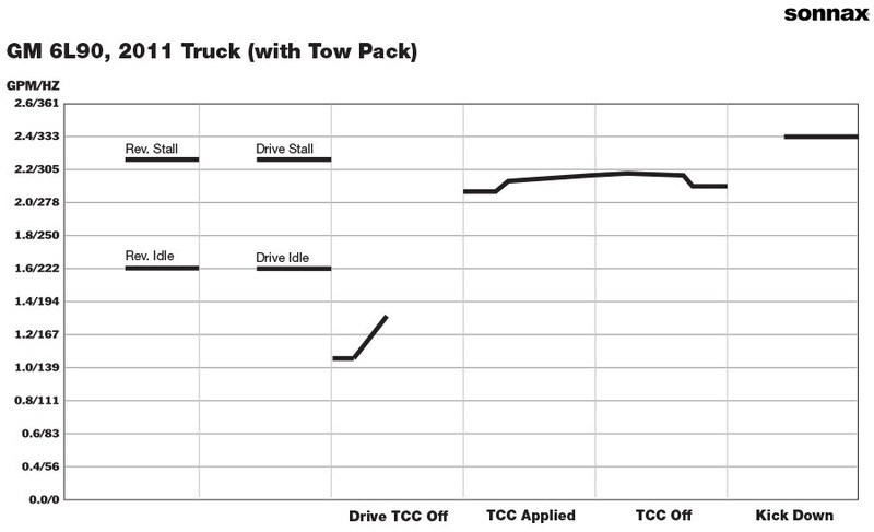
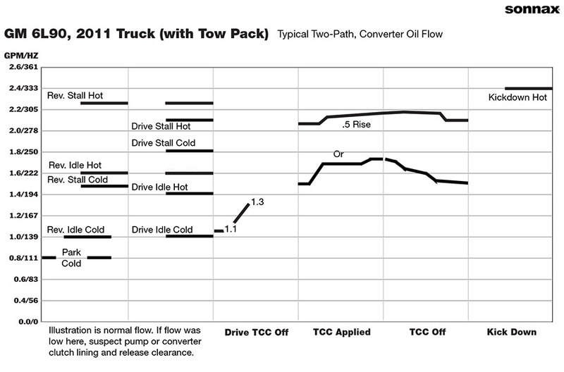
As release pressure is reduced, apply pressure is increased, which affects ATF flow through the converter. Let me repeat that: flow through the converter, not flow to the cooler. When the clutch is not applied, the clutch has moved away from the cover for oil to pass. This clutch release clearance is a restriction. Upon lockup, pressure clamps the clutch, but flow from the TC control valve goes to the cooler instead of the converter. Typically, flow has a significant increase at full lockup, as apply pressure is now “dead-headed.” Pressure is holding the clutch, but flow is no longer through the converter (Figure 3).
| Figure 3 – GM 6L90, 2011 Truck (with Tow Pack) SonnaFlow® Chart |
|---|
Condition: Normal Drive & TCC Control |
A scan tool and flow meter can be used to monitor TC solenoid activity and the change in flow. As the clutch applies and releases, the turbine RPM, solenoid amperage and slip speed can be monitored. This data verifies the condition of the clutch and valve control. Testing apply pressure is rarely accessible unless the valve body is tapped for gauges.
The three-path converter circuits require more depth of explanation, as there are two types of three-path converter.
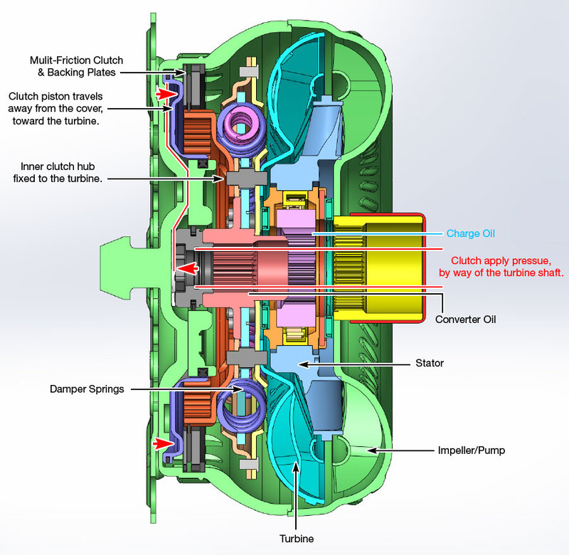
A turbine-fixed three-path has the TC piston splined to the turbine hub by way of a damper, and the piston travels toward the cover.
A cover-fixed three-path utilizes a multi-faced clutch built into the cover, similar to a transmission clutch drum or brake clutch.
The advantage of a three-path, turbine-fixed clutch is heat dissipation. As CBY (bypass, release) oil pressure is decreased, the clutch can maintain a modulated slip RPM. Slippage creates heat, but in this design there is continuous flow through CI (impeller) and the CT (turbine) circuit. Heat dissipation with slip is an advantage, but the division of those circuits is critical. Cross leakage, worn seals or circuit restrictions are detrimental and cause RPM cycling, no lockup or engine stall. Examples of problem areas include the Ford AX4S oil pump shaft and seals (Figure 4), Honda impeller hub O-ring failure or radiator restrictions.
| Figure 4 – AX4S Three-Path Stator & Pump Shaft |
|---|
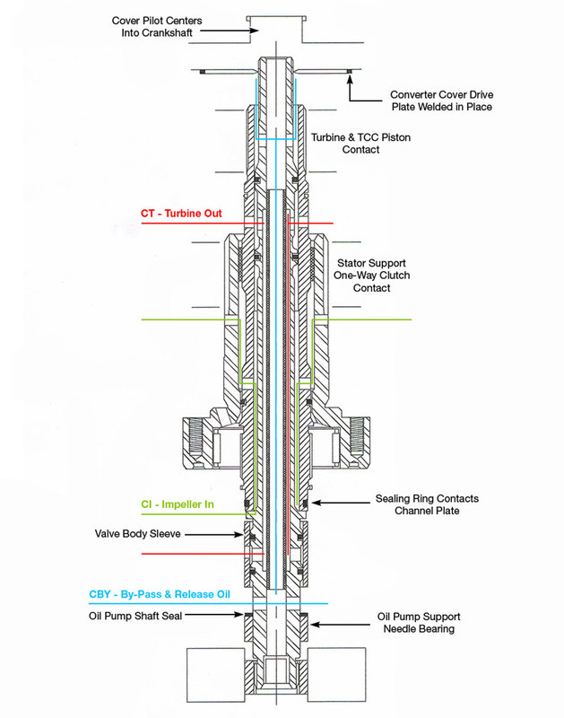 |
The Honda converter charge is directly from the main regulator valve. With this design, charge is often half of line pressure (Figure 2). Line pressure is priority oil, so circuit leaks or any drop in pump volume reduces converter release pressure, allowing the clutch to drag on the cover. Low converter charge combined with cross leaks results in TC lining failure. Increased cooler restriction opens the torque converter check valve, which reduces apply pressure. When it sticks open from repeated cycling, converter charge is low and the applied slip rate increases. Cooler and converter restrictions also cause pressure to react on valve spool differentials (reaction area). This can position them in a partial stroke, which limits flow in/out of the converter. Both conditions create overheated linings or converters. This will be further detailed part two of this article.
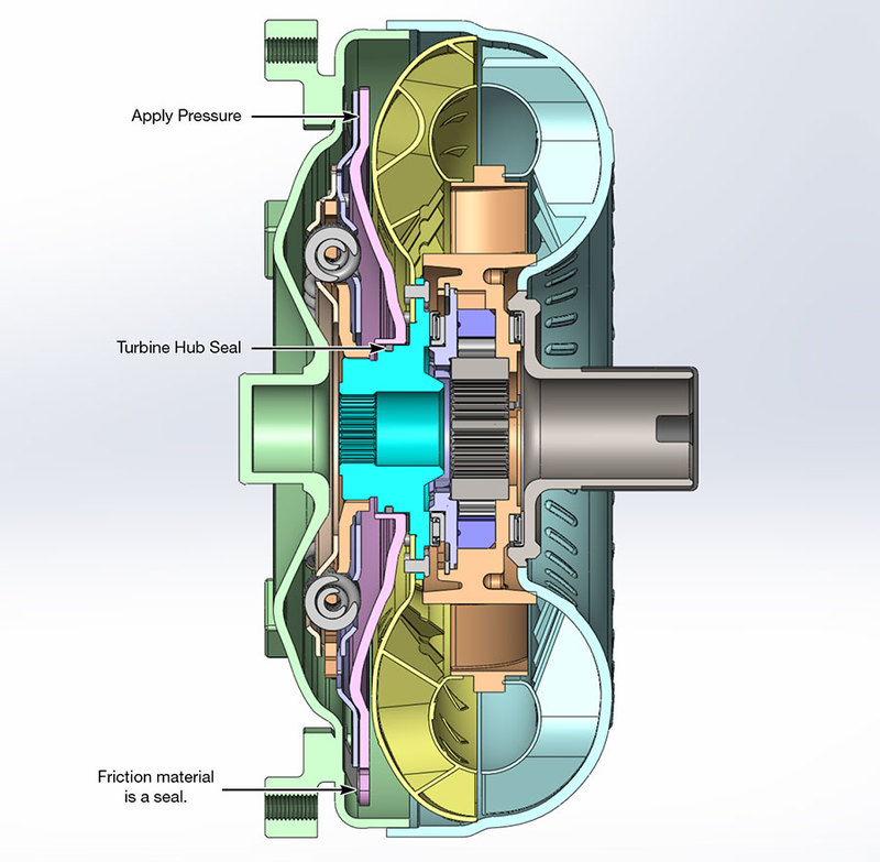
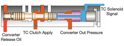
In the three-path, cover-fixed design, the clutch applies from pressure fed to the clutch through the turbine shaft (Figure 5).
| Figure 5 – ZF8 Mechanical View |
|---|
 |
All the previous clutches applied to the cover by exhausting release oil from the turbine shaft. In the cover-fixed design, the clutch applies by pressure feeding it. The cover-fixed paths are TC clutch apply, charge and converter out.
Diagnosing problems within a three-path converter requires knowing whether it is turbine-fixed or cover-fixed. Both types can be tested externally with a flow meter, and the flow data will appear similar. The three-path continually flows ATF, so we do not see the dramatic change in flow as the clutch piston moves off the cover. Both types of three-path will have a small deflection (.3–.7 gpm) in flow as the valves move to apply the clutch (Figure 6).
| Figure 6 – Honda 4- & 5-Speed, Odyssey, MAXA SonnaFlow® Chart |
|---|
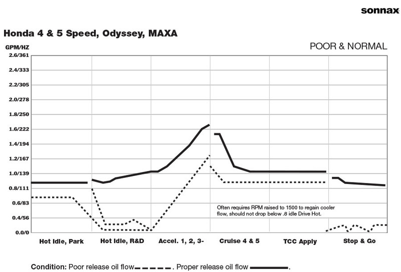 Concerns of high temperature: TCC lining failure; overheat code; TC 740 Code; TCC shudder. Operating temperature high 240–360° F prior to converter charge regulated pressure regulator valve. After valve body upgrades – 180° F maximum. |
This deflection indicates command, solenoid activity and valve movement. The scan tool can monitor slip rate and solenoid amperage as mentioned in the two path section. Verifying the specific clutch design requires an oil circuit or exploded view of the converter.
Flow is required in a two-path converter to hold the clutch piston away from the cover. Flow is required in both two- and three-paths to charge the converter and dissipate heat. Pressure is required in both to apply the clutch. So, you ask, what’s the difference, then, between a two- and three-path?
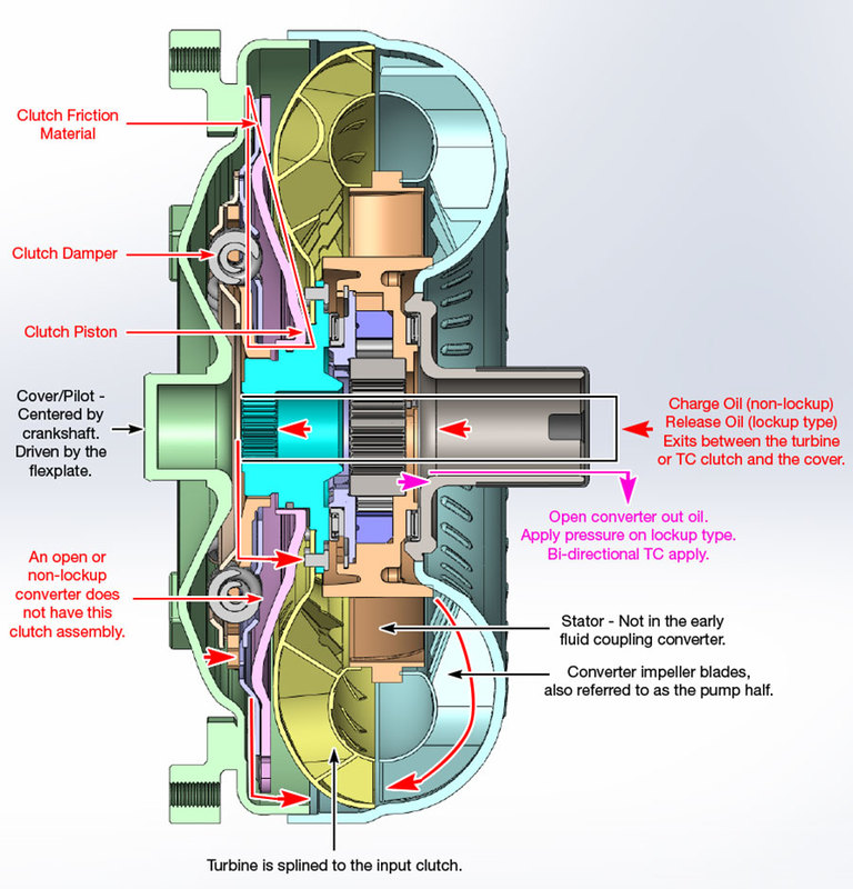
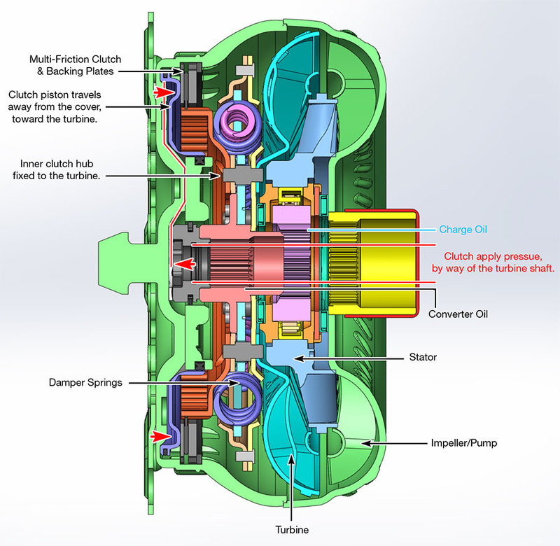
A two-path utilizes release and apply oil to control the position of the lockup piston. When a two-path clutch piston contacts the cover, flow is minimal across the friction surface (Figure 7).
| Figure 7 – Two-Path 6L90 Converter |
|---|
 |
The transition from the release oil holding the piston off the cover, to apply pressure loading the piston onto the cover, is the function of the clutch control/switch valve (Figures 8A & 8B).
| Figure 8A – 68RFE Clutch Control (TCC Off) |
|---|
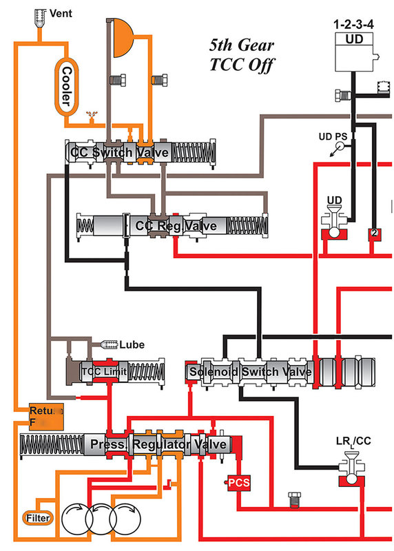 Image Courtesy of ATSG |
| Figure 8B – 68RFE Clutch Control (TCC On) |
|---|
Image Courtest of ATSG. |
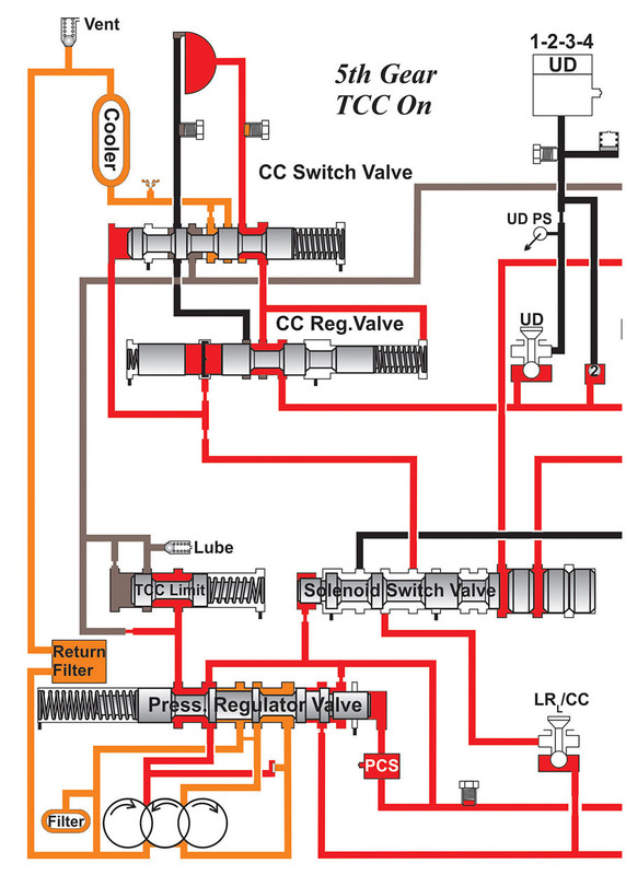
In some instances, a piston orifice or grooved friction allows a small amount of apply pressure to wash over and cool the clutch lining. This wash is a pressure drop, compensated by the TC regulator valve (Figure 9).
| Figure 9 – 6L90 Oil (TCC On) |
|---|
 |
torque increases and the TCM recognizes slip, the TC solenoid and TC regulator combine to control the slip speed. Slip speed or rate is the difference between engine RPM and turbine RPM.
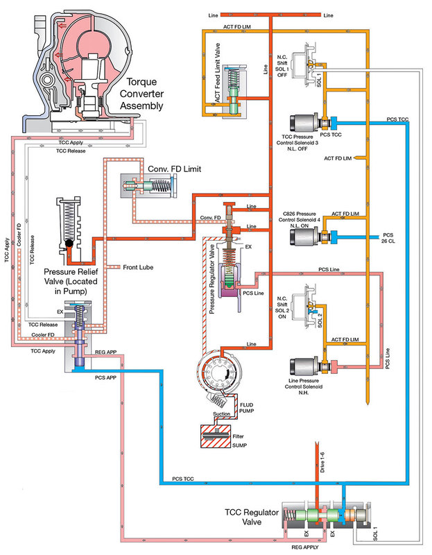
A three-path has a separate clutch apply path (Figure 10).
| Figure 10 – Three-Path ZF8 Cover-Fixed Clutch |
|---|
 |
Charge pressure and flow is uninterrupted during clutch apply on a three-path. Because of this flow, a three-path clutch can be applied under high torque or low speed. (The two-path can develop a shudder or friction failure when subject to those conditions.)
A converter will not charge properly if the pump output is low. Atmospheric pressure (Pa.) reacts on fluid, forcing it through the filter into the pump inlet. Upon rotation, the pump has a lower inlet pressure than Pa., so fluid is drawn in. If the case vent is plugged, the filter restrictive or fluid viscosity is high, flow into the pump will be low. If a surface is warped, air is pulled in easier than fluid and aerated fluid or cavitation occurs. No Pa. at pump inlet causes low pump charge, noise and low converter charge.
Isolating main regulator valve resonance from pump cavitation can be difficult. Some suggestions are to overfill, increase venting or pressurize the sump. Poor converter charge results in reduced torque and leads to transmission lube failure. A flow meter can isolate, then prove the fact and the fix. Poor charge is obvious, as the vehicle will not move until the converter is purged of air. The lack of lube until charged is not obvious.
Insufficient release allows the clutch to drag, which relates to rough idle and eventually friction overheat. Clutch release clearance is a dimension accounted for during the assembly of the converter. Poor clutch release can be identified with a scan tool as a surging turbine RPM or by flow, using a SonnaFlow® Cooler Flow Test (Figure 11). The best position to check release oil, or the cause of a dragging clutch, is in Reverse, during a hot idle.
| Figure 11 – 6L90 SonnaFlow® |
|---|
 |
In review, we noted apply pressure is a variable, controlled by amperage to the TC solenoid, which solenoid output moves the TC control and then the regulated apply valve. That’s a long sentence for a long sequence of events. The majority of two-path lockup circuits have the TC control stroke first to switch the oil path. Once the release path is exhausted, the apply path gradually loads the piston onto the cover. The TC control valve has a much lower spring rate and larger reaction area to ensure it remains stroked. Note the word “ensure” — what if the control valve does not stroke all the way? In some instances, the converter paths in and out are restricted by a partially stroked valve, resulting in a super-heated converter. The second reaction from the TC solenoid output is the position of the TC regulator valve. The regulator valve is continually moving, in connection with TCM slip control. That activity equates to bore wear. Bore wear might be addressed by installing a stronger regulator spring or blocking the apply valve into high apply pressure. This also results in a sequence of events:
We need to remember, line pressure feeds the converter regulator valve. By design, most valves limit apply pressure to the TC piston around 130 psi. If the apply pressure is modified and line pressure is elevated as well (by wear or modification) the clutch piston can receive 150-200+, pressure across the area.
The charge pressure of a ZF8HP is illustrated in Figure 12. PzT will decrease as the clutch applies, but PzT is not eliminated. Release pressure in the two-path is eliminated. Monitoring PzT will indicate if converter feed is sufficient and the TC valves have stroked. PzT is not checking the clutch apply circuit. Clutch apply maintains about 4 psi of pre-fill in this ZF8HP.
Note: A problem can arise in any three-path converter if charge pressure leaks into the isolated apply circuit. The extra pressure in the clutch housing is amplified by centrifugal force and crowds the clutch. The leak into apply can overwhelm an exhaust slot or relief in the valve body. Most three-paths do not have an apply tap, but we can check the circuit with an air test of the apply circuit in the case. On the bench we can use a turbine shaft. Fluid and air should not continue to leak into the charge or converter out circuit (Figure 12).
| Figure 12 – ZF8 TC Apply |
|---|
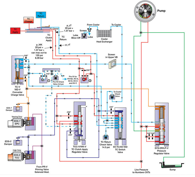 |
A restriction in the flow within the converter, (turbine or clutch) or radiator can affect the valve action (Figure 13).
| Figure 13 – Valve Ratio |
|---|
 |
Some valves have a circuit connected to either apply or to charge that cause the valve to stroke in relation to converter pressure, which improves balance and control. If the clutch lining was changed to a non-grooved type, or turbine washers changed or the radiator plugged from a previous failure, the TC apply can be very slow and a shudder or slip arise. In this instance, bypass the radiator and re-drive or install a flow meter and compare to a functional unit.
A common problem relative to many drivability issues is excess or low solenoid flow and pressure. We discussed the importance of a TC apply regulator valve. A solenoid regulator valve is equally important (Figure 14).
| Figure 14 – Solenoid Leakage |
|---|
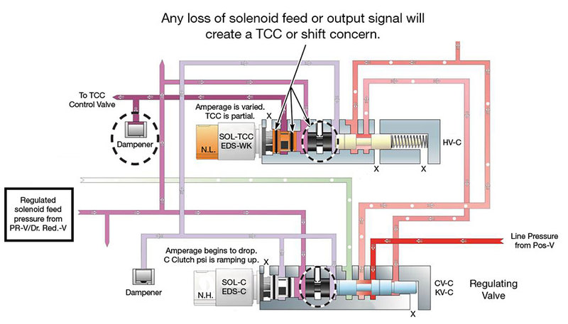 |
Too much pressure in causes too much pressure out, in this case premature lockup and slow release. Low pressure causes TCC shudder and slip.
Ensure you vacuum test all these regulator valves mentioned that affect converter feed and apply:
The main point to remember is in reference to the clutch. The two-path requires a good clutch friction to separate release and apply pressure. The three-path relies on seals and/or bushings to control the clutch apply. From the driver’s seat, we are not aware of the design, but a shudder or lack of lube is approached differently once we open them up for repairs.
Be sure to check out: Hydraulics Fundamentals Part V: Manual Valves.
Bob Warnke is Sonnax vice president of technical development and a member of the TASC Force (Technical Automotive Specialties Committee), a group of recognized industry technical specialists, transmission rebuilders and Sonnax Transmission Company technicians.
January 28, 2019
Zachary Richardson
February 26, 2019
Maura Stafford
March 26, 2019
Jim Dial
April 20, 2020
May 03, 2019
Bob Warnke
June 08, 2020
March 03, 2020
Jim Dial
March 26, 2020
John Varvayanis
December 17, 2020
Jim Dial
While Sonnax makes every effort to ensure the accuracy of technical articles at time of publication, we assume no liability for inaccuracies or for information which may become outdated or obsolete over time.