November 20, 2020
Hydraulics Fundamentals Part VI: Converter Limit Valves
John Varvayanis
Read Part I , Part II, Part III, Part IV and Part V of the Hydraulics Fundamentals series.
Pressure relief/limit valves perform a similar function to the regulator valves discussed in parts I and III of this Hydraulics Fundamentals series. These valves can appear in several forms and in different locations within a transmission. Pressure relief and limit valves can take the form of a spool valve as well as a simple checkball with a spring. As the name suggests, the pressure limit valve is designed to limit the maximum pressure within a hydraulic circuit.
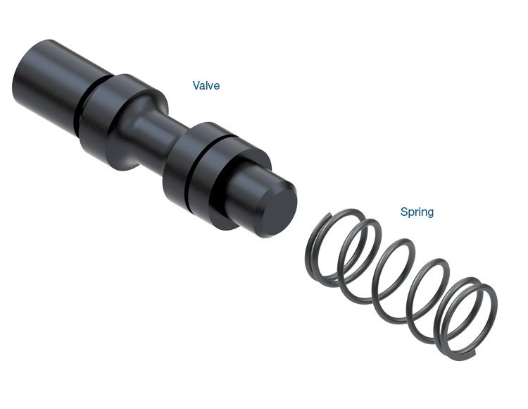
Shown in Figure 1 is a converter feed limit valve from a GM 6L80 or 6L90 transmission.
| Figure 1 — 6L80 Converter Feed Limit Circuit |
|---|
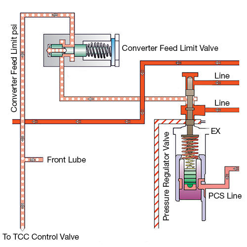 |
As you can see, this is a relatively simple valve. When the valve is in its rest position, the fluid from the pressure regulator valve passes freely around it to feed the TCC control valve. This fluid also passes to the inboard end of the valve through an orifice within the valve, and this pressure causes the valve to move against the spring. As the pressure builds, the valve strokes to a position that cuts off the converter feed fluid pressure through the valve to the appropriate limiting pressure as determined by the OEM. This also prevents fluid pressure from reaching the inboard end of the valve, thus allowing the spring force to stroke the valve inward again to re-establish flow to the TCC control valve. It is this back and forth movement that allows limiting of the converter feed pressure.
A similar valve is the solenoid pressure regulator valve, found in the Ford 4R70E and 4R70W series transmissions (Figures 2 and 3).
| Figure 2 — 4R70 Solenoid Regulator Valve Operating Correctly |
|---|
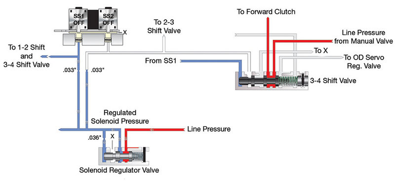 |
Line pressure enters the valve and, when the valve is at rest, the fluid is able to freely flow by into the SOLP circuit. As the pressure increases, the solenoid pressure (shown in blue) begins to push the valve to the right, which closes off the line pressure from the solenoid pressure to limit the maximum pressure in the solenoid circuit.
As the valve wears, it no longer seals properly and also begins to stick. When this happens, line pressure cannot be shut off, which leads to an increase in solenoid pressure. Shift solenoids 1 and 2 are normally open, and this increase in solenoid pressure floods the solenoids and causes the 3-4 shift valve to stroke to the right. The typical complaint connected to problems in the solenoid regulator valve in this family of transmissions is a neutral on take off (Figure 3).
| Figure 3 — Solenoid Regulator Valve Operating Incorrectly |
|---|
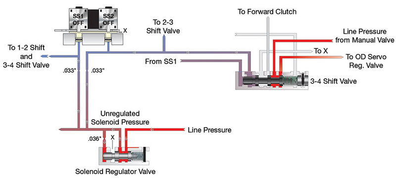 |
When at a stop in 1st Gear, solenoid 1 is on. When the solenoid regulator valve is stuck or worn badly, the excess feed pressure will cause solenoid 2 to flood as if it were turned on, which causes the 3-4 shift valve to stroke, turning off the forward clutch and leading to the neutral on take off.
The Chrysler 45RFE, 68RFE contains a more complex limit valve (Figure 4).
| Figure 4 — RFE TCC Limit Valve Circuit |
|---|
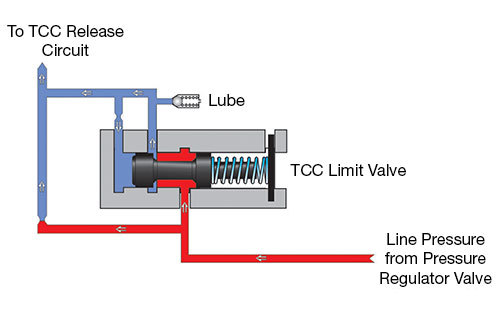 |
The hydraulic circuit around this valve contains two orifices, which serve to limit flow through the TCC limit bypass and reduce pressure spikes to the valve. Like the 6L80 valve in Figure 1, in the rest position, line pressure is allowed to freely pass the valve and enter the converter release limit circuit. Some of this fluid pressure passes through an orifice to the inboard spool on the valve as balance pressure. This pressure increase will cause the valve to stroke against spring force and block fluid flow through the valve, thus limiting converter release pressure to the amount set by OEM. However, fluid is never fully blocked, and it can continue to flow through the orifice below the valve in Figure 4, which maintains a small amount of flow to the release circuit at all times.
Figure 5 shows the TC limit valve for the Jatco/Nissan JF011E (RE0F10A) transmission.
| Figure 5 — JF011E TC Limit Valve Circuit |
|---|
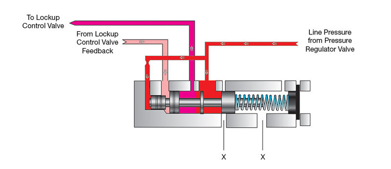 |
In this valve body, the TCC limit valve is closed at rest and will only move once the line pressure (shown by the red line) is high enough to overcome the spring force. This movement allows fluid to pass to the lockup control valve and on to the converter to apply the converter clutch. In addition, the limit valve gets feedback from the lockup control valve (shown by the pink line), which works with the line pressure to push the valve against the spring. This provides limiting pressure to the converter clutch apply circuit by allowing the valve to stroke far enough to exhaust excess line or converter clutch apply pressure.
Understanding how the pressure relief and limit valves work in different transmissions is key to determining the causes of different symptoms. In the 6L80 and 6L90, for example, if the converter feed limit valve is worn, it can prevent the valve from stroking, which leads to high converter pressure. Meanwhile, in the 68RFE, the TC limit valve tends to wear and bleed off excess fluid, which causes low flow in the converter circuit, which can cause low cooler flow and/or a stalling condition. Looking over the hydraulic diagrams of different valve bodies and pumps can really help in determining how wear in different valves can affect the system as a whole.
Be sure to check out: Hydraulics Fundamentals Part VII: AFL/Solenoid Modulator Valves.
John Varvayanis is a Sonnax design engineer. He is a member of the Sonnax TASC Force (Technical Automotive Specialties Committee), a group of recognized industry technical specialists, transmission rebuilders and Sonnax technicians.
Learn More
January 28, 2019
Hydraulics Fundamentals Part I: Main Pressure Regulator Valve Line-Ups
Zachary Richardson
February 26, 2019
Hydraulics Fundamentals Part II: Accumulators & Shift Feel
Maura Stafford
March 26, 2019
Hydraulics Fundamentals Part III: Secondary Regulators
Jim Dial
May 03, 2019
Hydraulics Fundamentals Part IV: Converter Clutch Control
Bob Warnke
March 03, 2020
Hydraulics Fundamentals Part V: Manual Valves
Jim Dial
April 20, 2020
Hydraulics Fundamentals Part VII: AFL/Solenoid Modulator Valves
June 08, 2020
Hydraulics Fundamentals Part VIII: Check Valves
December 17, 2020
Hydraulics Fundamentals Part X: Shift & Relay Valves
Jim Dial
Related Units
JF011E (RE0F10A) Transmission
45RFE Transmission
4R70W Transmission
68RFE Transmission
6L90 Transmission
6L80 Transmission
4R70E Transmission
Related Parts
Required
Recommended
Required
Recommended
6L45 • 6L50 • 6L80 • 6L90
Oversized Converter Feed Limit Valve 104520-11
-
Helps cure:
- High TCC slip RPM
- Code P0218
- Code P0741
- Overheated converter
- Inadequate lubrication
- Excess converter pressure
Required
Recommended
JF010E (RE0F09A/RE0F09B) • JF011E (RE0F10A)
Oversized TCC Limit & Lube Valve Kit 113741-04K
Also fits Mitsubishi F1CJA.
-
Helps cure:
- Engine stall on engagement
- No lockup
- Increased RPM during acceleration
- Ratio codes
- Poor performance
- Overheated fluid
- Poor fuel economy
- Poor lube oil control
While Sonnax makes every effort to ensure the accuracy of technical articles at time of publication, we assume no liability for inaccuracies or for information which may become outdated or obsolete over time.