Latch It: Latching Valves in the 6R60/80 & 6R140 Family of Transmissions
Looking back on childhood memories, you can probably recall Mom yelling from the kitchen, “Make sure you latch that screen door behind you!” when she heard you come in the front door after school. If you didn’t latch it shut, the wind would come along and the screen door would fly open because the pneumatic door closer was worn out. You wouldn’t want to make Mom mad, so you latched that screen door!
These days we are noticing the nomenclature of latching valves in the 6R60/80 and 6R140 family of transmissions. These valve trains are used in conjunction with a regulating valve to control the apply and release rate of a clutch or brake. The clutch latch valve and regulating valve are both controlled by an EDS or PWM type solenoid. This type of solenoid runs on a varied duty cycle, and the strategy for this duty cycle is adaptive.
The timing of the solenoids signal pressure and the integrity of these valve trains can make for a variety of different concerns, including delayed engagements, flared shifts, harsh shifts, bind-ups, no Forward or no Reverse, and of course the numerous solenoid performance and/or gear monitoring Diagnostic Trouble Codes. So the list is quite large, and the precise flow of the solenoid and hydraulic function of these valves has to be spot on or you will quickly have a return customer (and not a happy one).
Apply & Release Sequence of Forward/A Clutch
These hydraulic diagrams show the three-step sequence in applying the A Clutch, which in reality happens
in milliseconds.
Valves at Rest
The schematic in Figure 1 shows the clutch A latch valve, the clutch A pressure control valve and the VFS 1/A solenoid that controls the position of these valves. The valves are at rest: the A clutch off and the VFS 1/A solenoid - which is a normally low solenoid - at .50mA. as found in first-generation ZF6HP19/26/32 units, as these transmissions are very closely related and the same concerns would apply.
| Figure 1: Valves at Rest |
|---|
 |
Figure 2 shows the VFS 1/A amperage ramping up as it begins to apply solenoid signal pressure to the clutch A latch valve and the clutch A pressure control valve. Solenoid signal pressure is ramping up at this midway amperage range of .200-500mA, which partially strokes the clutch A regulating and latch valve. This action opens a port on the regulating valve to connect line pressure from the manual valve in the Drive position to Forward/A clutch apply, which is then sent to a port that is opened up by the position of the clutch A latch valve. This passage connects to the spring side of the clutch A pressure control valve.
This midway point is the regulating sequence in A clutch application. The Transmission Control Module (or PCM on some models), monitors the amperage of the solenoid and the Input speed sensor to switch this midway point to full application of the A or Forward clutch.
| Figure 2: Solenoid Signal Pressure Applied |
|---|
 |
Figure 3 shows the solenoid amperage ramping up to .850mA, which in turn moves the clutch A pressure control valve and clutch A latch valve into a position, closing off the connection to the spring side of the regulating valve. The Forward/A clutch is fully applied.
| Figure 3: Forward/A Clutch Fully Applied |
|---|
 |
Now that we know the sequence and complexity for clutch and brake application, it is easy to see that there are many possibilities and problem areas which can cause the above concerns.
| Figure 4 | Figure 5 |
|---|---|
 |
 |
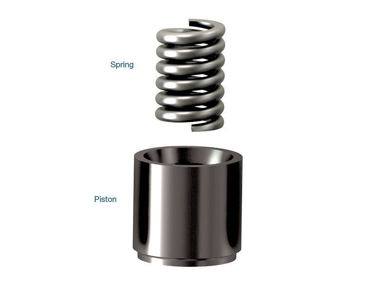
The EDS PWM solenoid is a common culprit, as debris has been a factor with flow problems. The circuit diagrams also show the damper/accumulator piston that is in the path of solenoid signal pressure. This damper/accumulator has a rubber plug that helps absorb the pulse in the solenoid signal pressure leading to the regulating and latch valves, which tends to flatten out over time. Sonnax's patented accumulator piston kit 95740-15K is a direct replacement for the OE lineup and incorporates a spring and piston to replace the previous design (Figure 4).
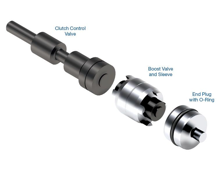
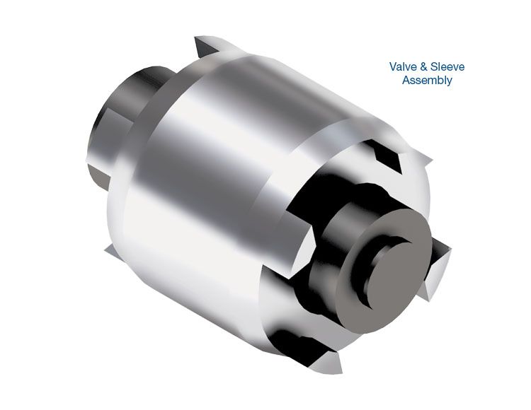
Another common problem area is the clutch A control pressure regulator valve. This valve (as shown in Figures 1-3) controls the apply rate of the A clutch, and - including the boost valve and sleeve - is known for bore wear. Wear in this bore can specifically cause Drive engagement delays, harsh applications and downshift clunks from 6th or 5th to 4th gear. Sonnax offers oversized clutch A control valve kit 95740-09K and clutch A control boost valve kit 95740-21K (Figure 5) for repairs.
This family of transmissions, whether they belong to Ford or ZF, use this type of application strategy with similar valve trains for multiple clutch and brake applications. It’s important to keep in mind that all of the components are connected, as this can help get to the root cause of transmission problems more quickly.
Now that we see the function of the regulating valve worn out like the pneumatic door closer, and the latch valve, which closes the opening to the spring side of the regulator valve, it makes it easier to close the door on a common complaint and latch it behind you.
Related Units
Related Parts
Required
Recommended
6R100 • 6R60 • 6R75 • 6R80 (2009–2014) • 6R80 (2015-Later) • ZF6HP19 • ZF6HP26 • ZF6HP32
Oversized Clutch A Control Valve Kit 95740-09K
-
Helps cure:
- Downshift bind-ups
- Flare shifts
- Excess clutch overlap & clutch distress
- Pressure control out-of-range codes
Required
Recommended
6F35 (Gen. 1) • 6F35 (Gen. 2) • 6F35 (Gen. 3) • 6R100 • 6R140 • 6R60 • 6R75 • 6R80 (2009–2014) • 6R80 (2015-Later) • 845RE • 850RE • CFT30 • ZF6HP19 • ZF6HP21 • ZF6HP26 • ZF6HP28 • ZF6HP32 • ZF6HP34 • ZF8HP45 • ZF8HP50 • ZF8HP55 • ZF8HP70 • ZF8HP75
Accumulator Piston Kit 95740-15K
Required
Recommended
6R100 • 6R60 • 6R75 • 6R80 (2009–2014) • 6R80 (2015-Later) • ZF6HP19 • ZF6HP26 • ZF6HP32
Clutch A Control Boost Valve Kit 95740-21K
While Sonnax makes every effort to ensure the accuracy of technical articles at time of publication, we assume no liability for inaccuracies or for information which may become outdated or obsolete over time.