Bushwhacked! Keys to Avoiding Preventable Bushing Problems
Brian Wing
Bushings have always played an important role in automatic transmissions. We’ve all seen the consequences of wiped-out bushings, we’ve replaced damaged bushings and the components that ride on them, and preventative bushing replacement during rebuild is common. Usually, as technicians we don’t often think too much about bushings until we come across one that’s been cooked. There are also important factors concerning bushings that most of us don’t contemplate during bushing selection and installation; considering these factors is fundamental to ensure long, trouble-free bushing performance in all your builds.
Ever wonder why some transmissions seem to have bushings that wear out faster than others? Ever have a comeback due to a failed bushing? What caused the bushing to fail? Of course, some problems are caused by diminished lube supply or misaligned parts, but what other preventable causes of bushing failure exist, and how can we minimize our chance of being burned by a seized or spun bushing — or bushing-related failure — during our warranty period? With a bit of insight into bushing purpose, design and most-favorable operating characteristics, it is possible to lengthen bushing life, improve fuel economy and keep the gear train properly aligned so that other (seemingly) non-related components don’t wear out prematurely and result in a comeback.
Only the Strong Survive
To work successfully and live a long life, bushings in automatic transmissions need to be designed within the following general parameters:
- Must support large forces generated by gears and rotating components— loads up to 1,400 psi
- Must handle speeds of up to 9,500 RPM (top planetary speed)
- Must endure temporary operation with low/no lube oil
- Must minimize drag/heat/power loss due to friction and “off” conditions such as component misalignment due to manufacturing anomalies
- Must provide optimal clearance to the supported shaft in order to achieve proper fluid film thickness between bushing and shaft journal
- Must be able to seal circuits (where required)
- Must resist corrosion
With these constraints in mind, design engineers have a raft of items to consider in their effort to produce a bushing that can stand up under punishing conditions.
Bushing Design: The Engineer’s Dilemma
During the design process, bushing material selection is the first consideration an engineer must ponder. A material is chosen based on characteristics that most ideally suit the intended application. However, all material choices are compromises; each material has different attributes, and one material may be better suited for a particular application than another. In automatic transmissions, the following material attributes must be considered:
- Fatigue Resistance — The greater load-carrying capacity a material has, the greater its resistance to fatigue.
- Score and Seizure Resistance — The ability of the material to resist scoring and welding to the mating component, particularly under low- or no-oil conditions.
- Conformability — The ability of the material to compensate for component misalignment and deflection.
- Embedability — The capability of the material to absorb and sequester foreign particles suspended in ATF.
- Corrosion Resistance — The ability to withstand corrosive media that develops in ATF over time.
Any engineer would desire a material that rates highly in all these areas, which is not possible; tradeoffs must be made. There are four general material categories from which to choose, each with many possible combinations of base material:
- Lead/Tin-Based Babbitt — Relatively soft; poor fatigue resistance, which worsens with increased temperatures. Excellent conformability, embedability and seizure resistance. Good corrosion resistance.
- Copper/Lead (Bronze) — High fatigue resistance; slightly lower conformability, embedability and seizure resistance than babbitt. Fair corrosion resistance.
- Aluminum/Tin, Aluminum/Silicon, Aluminum/Lead — High-fatigue resistance; mixed score and seizure resistance; conformability and embedability considerably lower than babbitt and bronze. Excellent corrosion resistance.
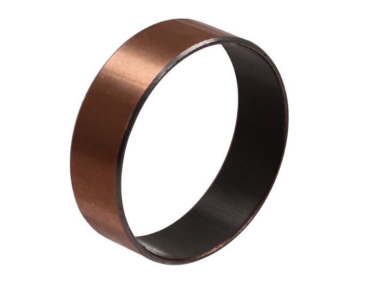
- Polymer-Impregnated Bronze (PTFE) — Good fatigue resistance; excellent score and seizure resistance; conformability very good, embedability lower than bronze. Excellent corrosion resistance. Large tolerance window for low- and no-oil conditions.
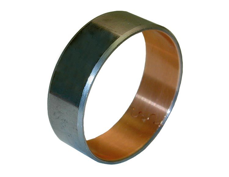
Whichever material the engineer chooses, most often the bushing will be designed with a steel backing for optimal retention in the housing bore. Steel backing also increases fatigue resistance and ease of installation. If no steel backing is incorporated, not only can retention suffer, the bushing can often distort under the force of installation and possibly cause fitment problems with the mating shaft. The most common materials in use today are steel-backed bronze, aluminum and PTFE.
Important Material Notes
Aluminum bushings have a thin coat of tin, silicon or lead on the load-bearing surface. While this surface provides excellent anti-score and anti-seize properties, it is very easy for that layer to be damaged in a heartbeat during low- or no-oil situations which commonly occur in transmissions. When that happens, the aluminum material that is exposed to the riding shaft fails by seizing very rapidly. Thus, aluminum bushings are not a good idea for areas where lubrication is not immediately and continuously available.
The second note concerns PTFE-coated vs. PTFE-impregnated bushings: the method of manufacture makes all the difference between a good bushing and one that can fail catastrophically. For these bushings to be effective, the PTFE layer must be sintered (impregnated) into a bronze middle layer, with steel backing. Sintering diffuses the PTFE molecules completely throughout the microstructure of the bronze, locking them together at the atomic level. If the PTFE layer is not sintered — i.e. adhesive or thermal spraying is employed to attach PTFE to the bushing — the PTFE layer will often separate or de-bond from the backing during operation, allowing seizure. PTFE foundation is analogous to our jaws — without good roots, we’d lose an awful lot of teeth.
Shaft Diameter, Wall Thickness & Chamfers
Shaft diameter is, of course, a key input to bushing design. A proportionate relationship between supported shaft, wall and length is always desirable. Consequently, wall thickness that is not tightly controlled can result in a bushing ID that does not mate well with the shaft, allowing misalignment of components and possible lube problems. Wall thickness is also important for bushing retention in the housing.
For ease of installation, OD and ID chamfers of a specified angle are necessary. They guide the bushing into the bore, and the shaft into the bushing. If any of these factors are specified incorrectly or not considered at all, a lower quality bushing will result.
Is This Thing Groovy, or What?
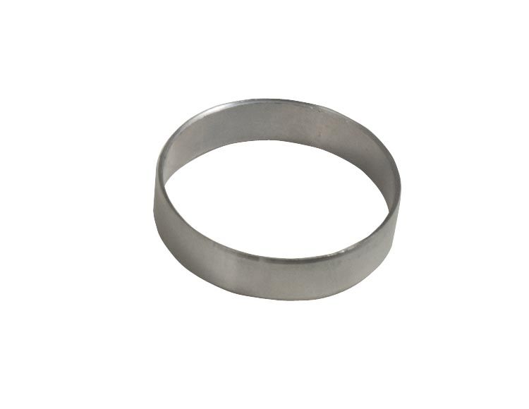
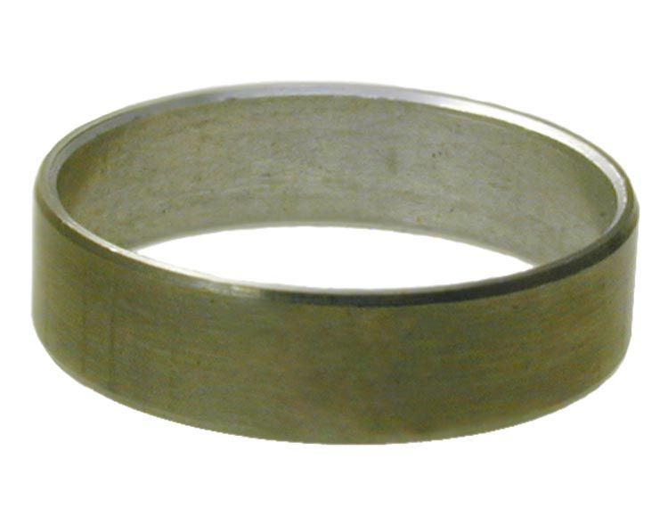
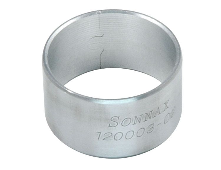
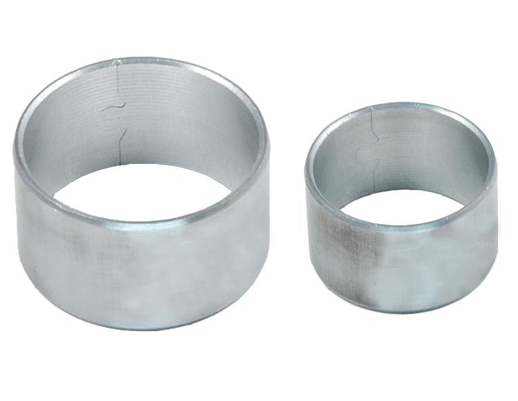
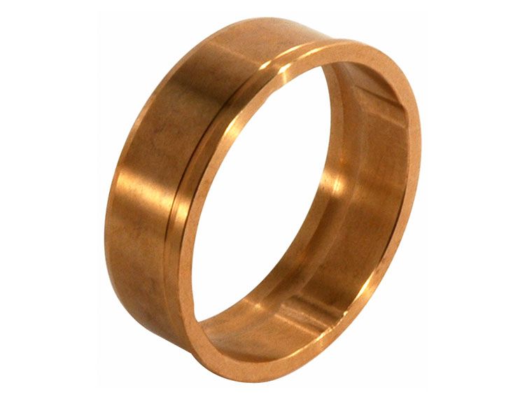
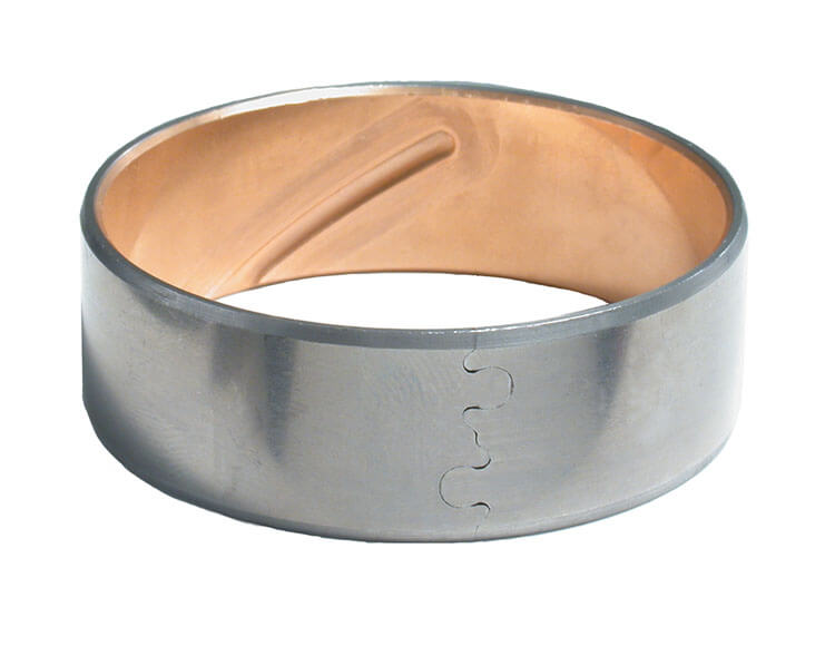
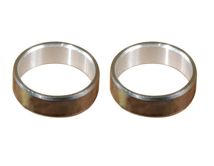
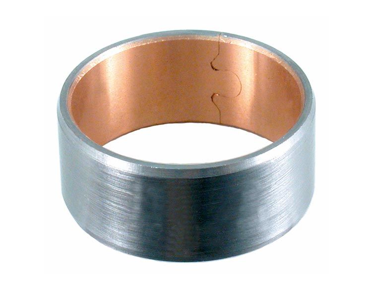
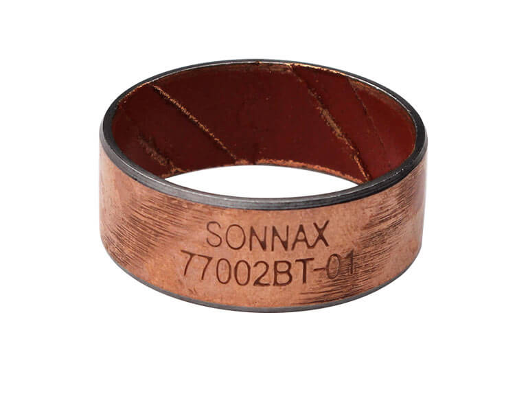
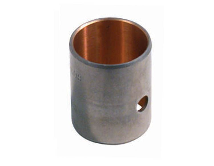
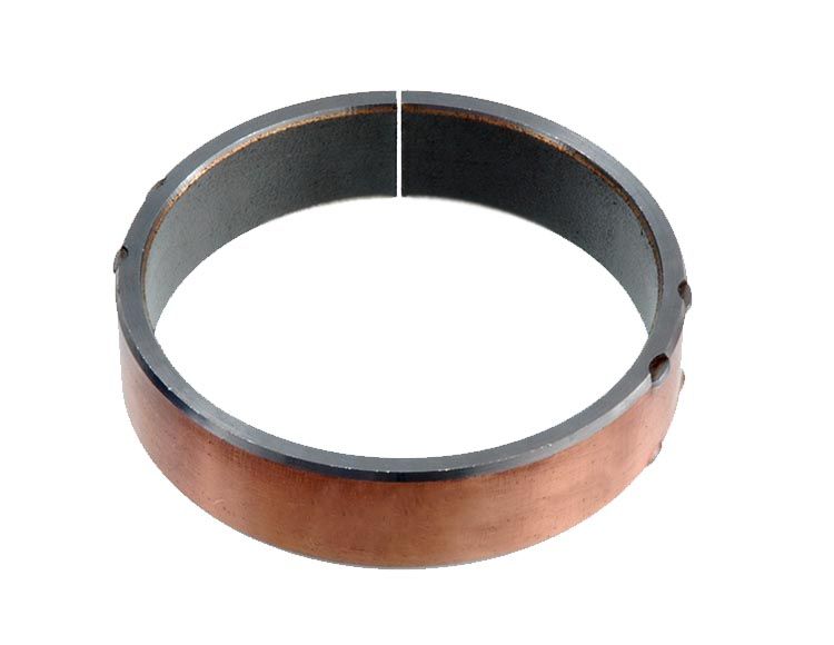
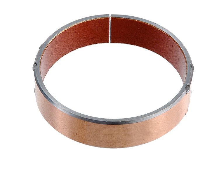
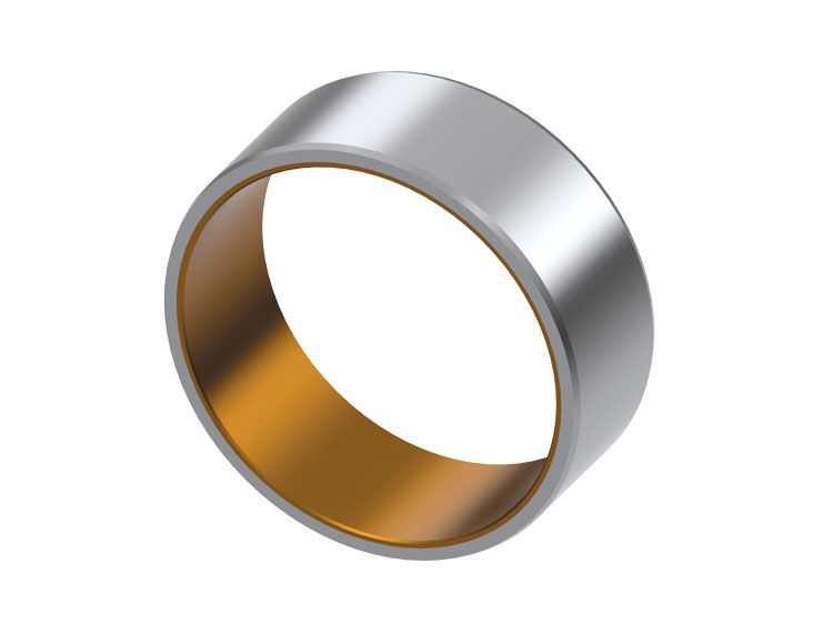
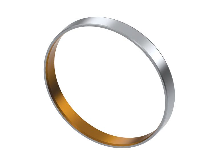
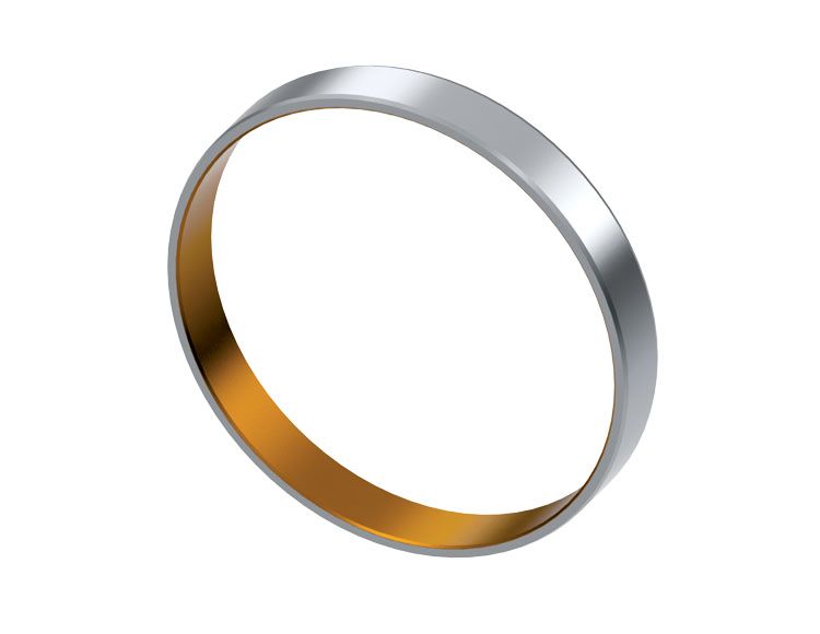
To groove or not to groove is an important design consideration. Grooves in the bushing ID are not always used, but they are utilized in many applications to improve lubrication (Figure 1).
| Figure 1 — Bushing with Groove |
|---|
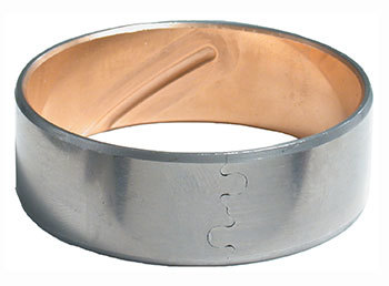 |
Groove design can be very complicated, but basically depends on lubricant type, source and quality as well as operating conditions and bushing dimensions. Grooves are also often used as a pumping mechanism, whereby the spinning shaft pumps oil through the bushing groove to lubricate the bushing and/or the component beyond the bushing.
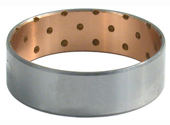
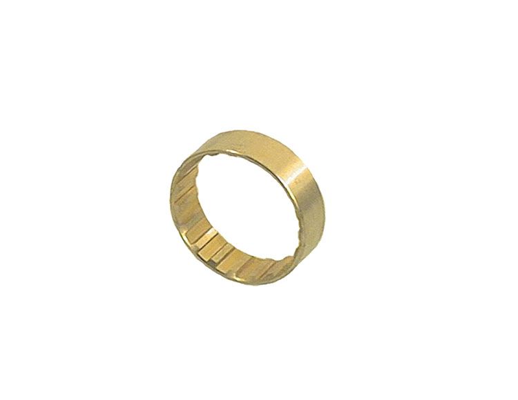
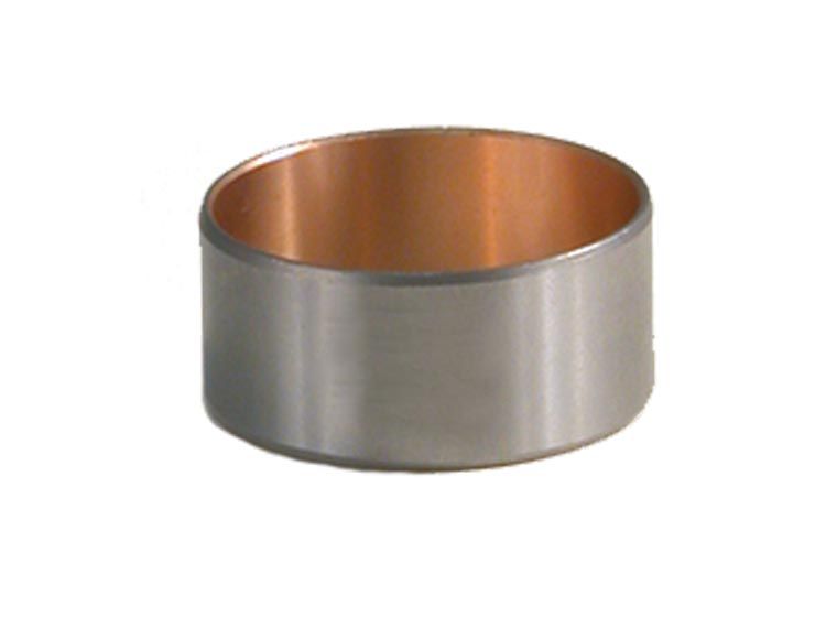
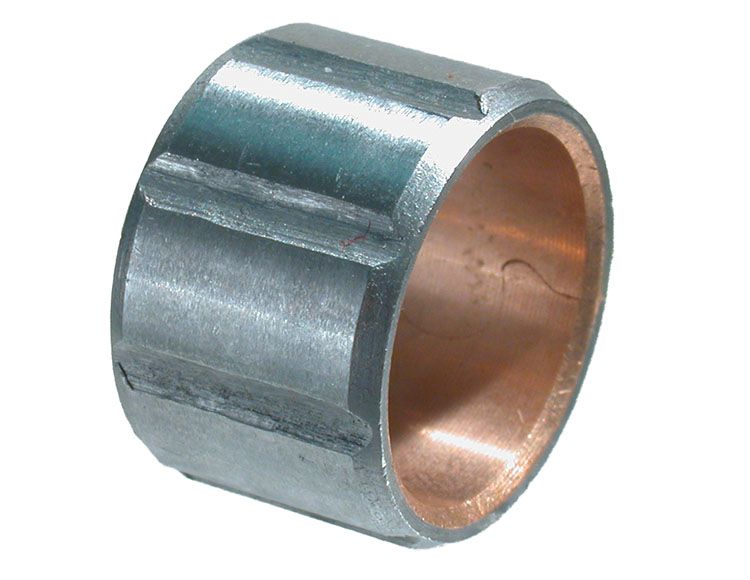
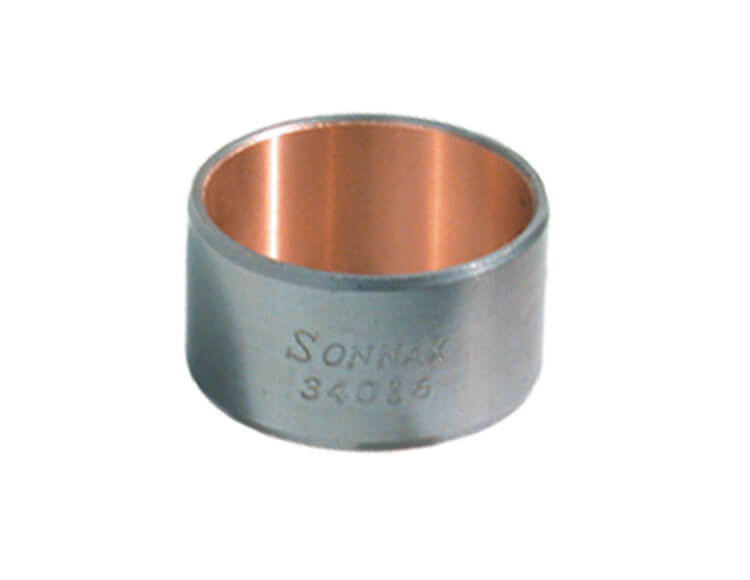
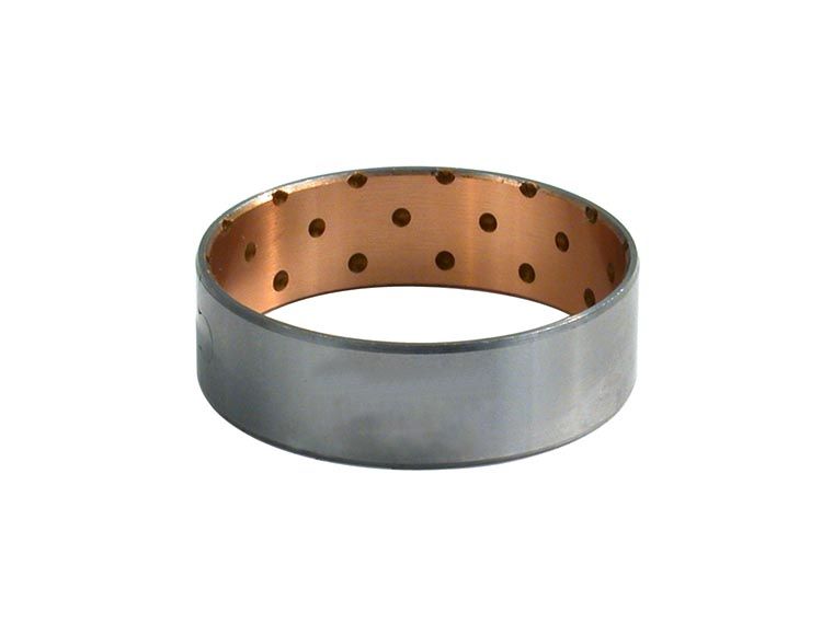
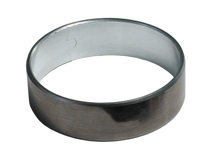
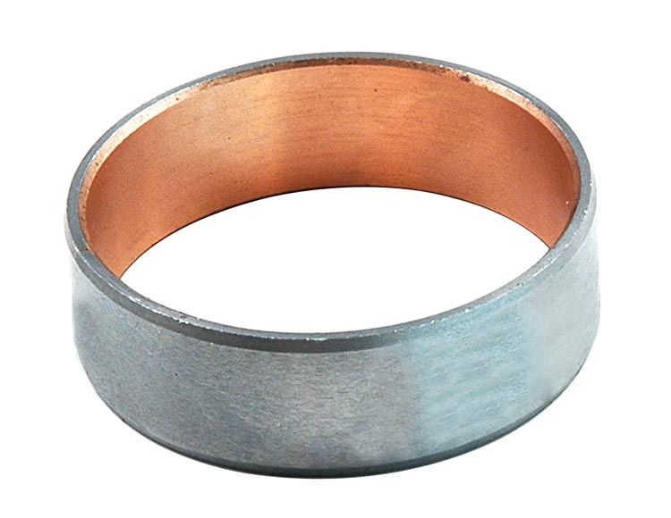
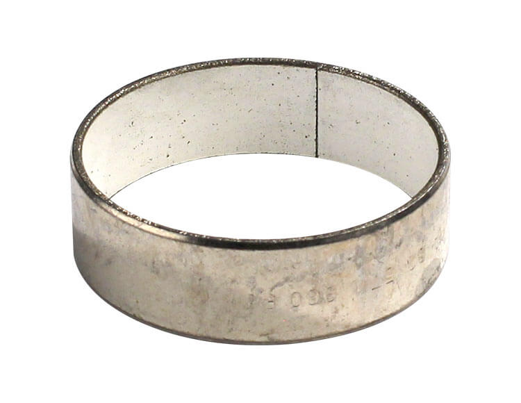
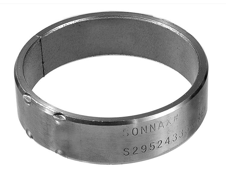
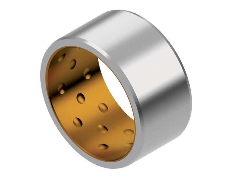
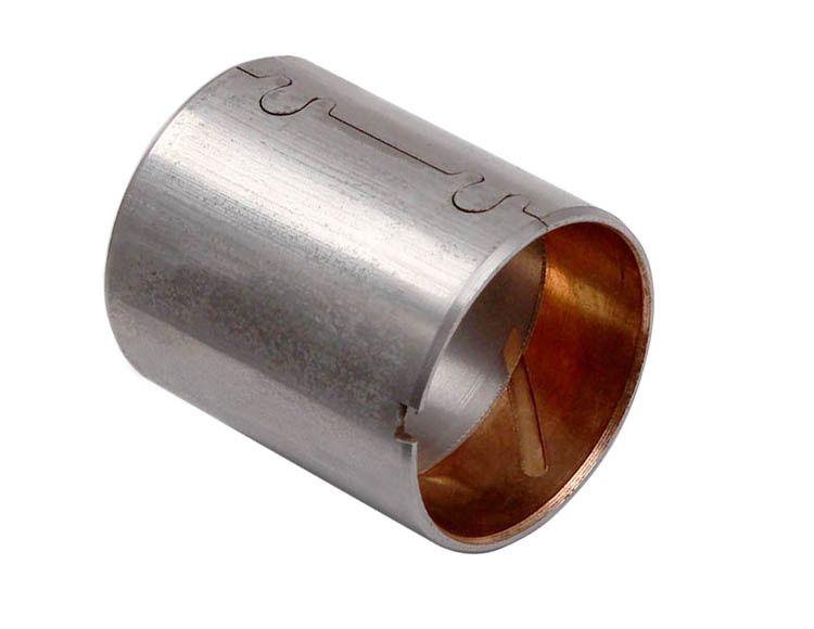
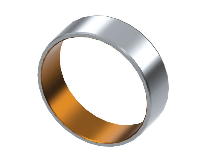
In many applications, periods of inactivity allow much of the ATF to disappear from the bushing. In these cases, ball indentations can be coined into the bushing surface, which act as small oil reservoirs. These reservoirs keep lubrication available to the bushing during start-up, until normal lubrication is restored (Figure 2).
| Figure 2 — Bushing with Indentations |
|---|
 |
Bushing & Mating Shaft Finish
Excessive roughness on the bushing and/or mating shaft is a leading cause of bushing wear and ultimate failure. An engineer can control the surface finish of the bushing, but the shaft it will be used with is another question. For optimal results, the load surface of the bushing should be less than 25 micro-inches RMS, while the shaft journal should be 8–12 RMS. Since load capacity is directly related to shaft surface finish, a properly prepped shaft will raise fatigue resistance while preventing premature wear of the bushing.
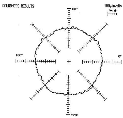
A shaft journal can have acceptable finish, but still wear out bushings due to excess “waviness” of the journal surface. This waviness is also known as grind chatter and occurs during the manufacturing grind process. Figure 3 shows a measuring micro-trace of a 4L80-E main shaft journal that caused bushings to wear out rapidly and repeatedly; quickly prepping this shaft by minimizing the chatter ridges restored normal operation.
| Figure 3 |
|---|
 |
Though the design of a bushing is considerably more complex than the basic information laid out here, we now have a general picture of the main considerations involved in producing a quality bushing. However, no matter how good the bushing design and manufacture might be, it cannot operate successfully unless the environmental conditions it will live in are favorable. The torch is now passed to the bushing installer.
Escaping the Kill Zone
The following recommendations will greatly lower your chances of being caught in a surprise bushing-attack during your warranty period:
- Realize that worn (or poorly made) bushings are the cause of problems from circuit leaks to component misalignment, clutch failure, broken components, friction losses, etc.
- Ensure the lubrication circuit operates normally. Vacuum test appropriate control valves and replace with oversized as necessary. Ensure lube passages are unrestricted.
- When selecting replacement bushings, choose a manufacturer with a reputation for tight tolerance specs, as shaft to bushing clearance is key to lubricant film thickness and part alignment. This is especially critical for circuits that use a bushing to seal part of a circuit. An example of bushings sealing circuits are those at the “E” clutch in ZF6HP units; most of us by now are familiar with the drivability problems and the 4F85 ratio monitoring code these units throw when the rear stator bushing wears out. Because the OE bushings utilize a less-than-optimal material in those ZF applications, this happens quite often.
- In most cases, forget bushings that are not steel-backed. The lower fatigue resistance, diminished retention properties and possibility of distortion during installation make non steel-backed bushings too risky for many applications.
- When installing bushings into aluminum housing bores, dress the leading edge of the bushing chamfer before installation. This will prevent galling of the aluminum bore.
- If you use a driver and hammer to install bushings, a change of practice is recommended. We’ve all done it — and gotten away with it many times — but the fact is that precision bushings can distort when driven in, causing fit and performance issues. Shock loads from driving tend to deform bushings (some more than others). Instead, always use an arbor press, which protects and preserves the integrity of the bushing ID and chamfers. Purchase or make dedicated bushing installers to use with the arbor press; replace any of these if they get dinged or scratched. Lightly lube the bushing before pressing.
- For bushings that handle high loads, use sleeve retainer or carefully stake them in after installation to prevent possible spinning.
- Prep the shaft journals and housing bores prior to installation. For best retention, the housing bore can be finished to 60–125 micro-inches RMS. For shaft journals, optimal finish is 8–12 RMS. You can do this easily by hand with the appropriate grit emery cloth; 60 grit will work just fine in the housing, and 400 grit will drop you right on the dead nuts for a shaft journal (Figure 4).
Figure 4
| Grit Size | RMS (Micro-Inch) |
|---|---|
| 36 | 160 |
| 60 (Use on Housing) | 98 |
| 120 | 58 |
| 180 | 34 |
| 240 | 17 |
| 320 | 14 |
| 400 (Use on Shaft) | 10 |
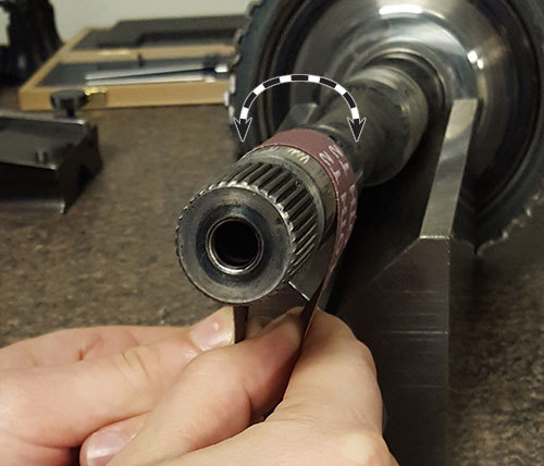
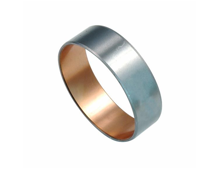
- We’re not trying to remove material here, so keep a light touch and just kiss the surface to get the best results. For the shaft, rotate the emery cloth back and forth around the axis of rotation (Figure 5).
| Figure 5 — Prep Shaft Journal With Emery Cloth |
|---|
 |
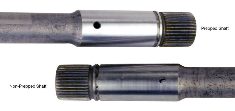
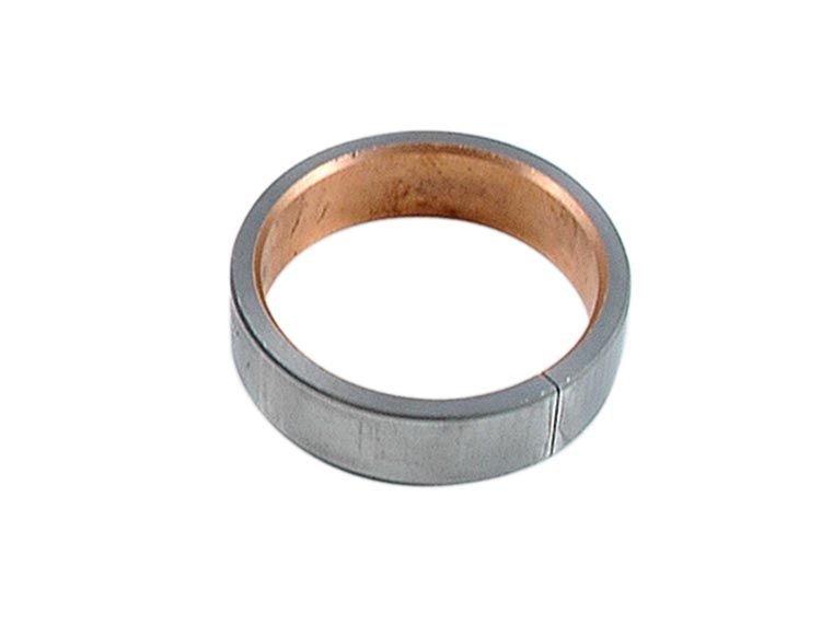
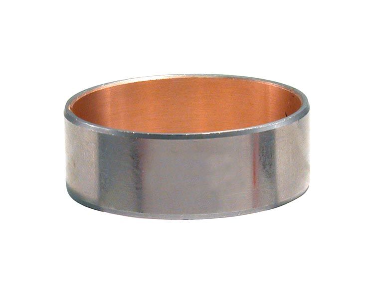
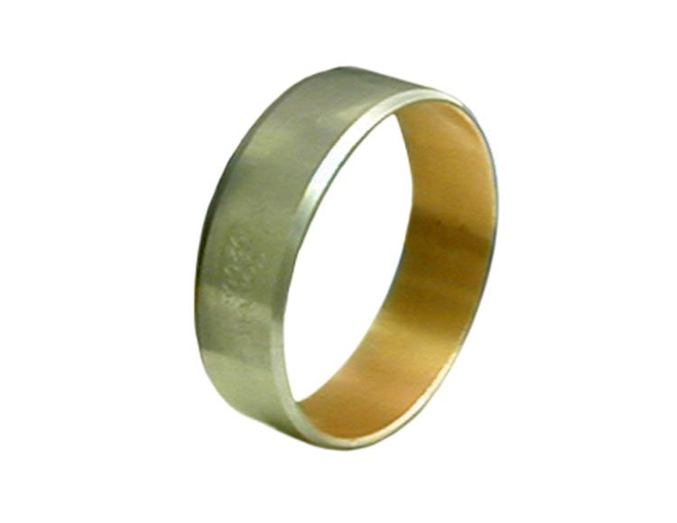
- Don’t forget to clean out all lube holes and passages afterward. Figure 6 shows one prepped and one non-prepped shaft. Which one would you prefer to install in your build?
| Figure 6 — Prepped Shaft vs. Non-Prepped Shaft |
|---|
 |
- Always use manufacturer-recommended oil, which the bushing was specifically designed to be run with. The right oil must be used to maintain the desired oil thickness between bushing and shaft, and to protect the shaft as it spins.
- Dirt is the worst enemy of a bushing. Be relentless about keeping the unit clean during service.
- Ensure all chassis grounds are intact and clean, with no impermissible voltage drops. If voltage can’t get to ground because of too much resistance in the designed path, it will find another way to get there — often damaging bushings in the process.
Another Bullet Dodged
Bushings are just one of many things competing for our attention during any rebuild; it can be easy to lose sight of their importance when we’re trying to track down the cause of a problem that is completely unrelated. But it pays to always remember the significant role they play in every transmission that comes across your path, regardless of the reason it is on the bench. Selecting the highest quality bushing available for your application, taking the time to prepare the mating shaft/housing bore and using preferred installation methods are fundamental steps in your never-ending quest to fend off prematurely worn bushings and bushing-related comebacks.
Brian Wing is a Sonnax product development manager for driveline and transmission components. He is a member of the Sonnax TASC Force (Technical Automotive Specialties Committee), a group of recognized industry technical specialists, transmission rebuilders and Sonnax technicians.
Related Units
Related Parts
Required
Recommended
68RFE
Center Pump Gear Bushing 72530B-03
Center Pump Gear
- Material: Steel backed aluminum
- Bushing Style: Precision
-
Helps cure:
- Pump gear wear or fracture
- Scored surface where center gear pump pilot passes through pump body
- Noise concerns
Required
Recommended
AL-4 • DPO
E1/E2 Clutch Drum Bushing 120002
E1/E2 Clutch Drum
- Bushing Style: Precision
- Material: Steel-backed aluminum alloy
-
Helps cure:
- Burnt clutches
- Excess hub-to-bushing clearance
- 2nd Quality poor
- 2nd Erratic
Required
Recommended
AL-4 • DPO
Pump Bushing 120001
- Bushing Style: Precision
- Material: Steel-backed aluminum alloy
- Width: 0.533"
- Shaft Dia.: 2.142"
- Housing Bore: 2.241"
-
Helps cure:
- Leaking front seal
- Low pump volume
- Delayed engagement
- Converter shudder & TCC slip
Required
Recommended
AL-4 • DPO
Pump Stator Bushing 120003-01
Small bushing, fits units '00-later.
- Bushing Style: Precision
- Material: Steel-backed aluminum alloy
- Width: 0.624"
- Shaft Dia.: 0.926"
- Housing Bore: 1.023"
-
Helps cure:
- Worn pump stator bushings
- Excess turbine shaft-to-stator bushing clearance
Required
Recommended
AL-4 • DPO
Pump Stator Bushing 120003-02
Large bushing, fits units '00-later.
- Bushing Style: Precision
- Material: Steel-backed aluminum alloy
- Width: 0.628"
- Shaft Dia.: 1.021"
- Housing Bore: 1.118"
-
Helps cure:
- Worn pump stator bushings
- Excess turbine shaft-to-stator bushing clearance
Required
Recommended
AL-4 • DPO
Pump Stator Bushing Kit 120003K
Pump stator, small and large bushings, fits units '00-later.
-
Helps cure:
- Worn pump stator bushings
- Excess turbine shaft-to-stator bushing clearance
Required
Recommended
40TE • 40TES • 41AE • 41TE • 41TES • 42LE • 42RE • 42RH • 42RLE • 62TE • A670 • A904
Pump Bushing 12502-01
- Bushing Style: Precision
- Material: Steel-backed bimetal
- Width: 0.535"
- Shaft Dia.: 1.498"
- Housing Bore: 1.619"
-
Helps cure:
- Pump seal leakage
- Pump noise
- Loss of prime
- Low pump volume
- Low cooler flow
- TCC codes
- Switch codes
Required
Recommended
Required
Recommended
4L80-E • 4L85-E • TH400
Case Bushing 34006-SP
- Material: Bronze
- Bushing Style: Precision
- Width: 0.630"
- Shaft Dia.: 2.006"
- Housing Bore: 2.129"
-
Helps cure:
- Bushing walks out
Required
Recommended
4L80-E • 4L85-E
Stator Support Bushing 34016-W
- Bushing Style: Precision
- Material: Steel-backed bimetal
- Width: 0.675"
- Shaft Dia.: 1.123"
- Housing Bore: 1.244"
-
Helps cure:
- TCC slip codes
- No lockup
- Overheated fluid
- No Overdrive
Required
Recommended
AT-540 • Powerglide • Powerglide, Cast Iron • TH350 • TH350C • TH400
Pump Bushing 34034T-01
Required
Recommended
4L60 • 4L60-E • 4L65-E • 4L70-E • Powerglide • TH350C • TH400
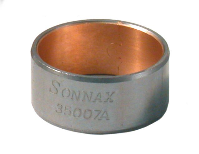
Stator Support Bushing 35007A
- Bushing Style: Precision
- Material: Steel-backed copper alloy
- Width: 0.500"
- Housing Bore: 1.121"
- Inner Dia.: 1.004"
- Shaft Dia.: 1.002"
-
Helps cure:
- Bushing wear
- Bushing failure
Required
Recommended
4R100 • 4R70E • 4R70W • 4R75E • 4R75W • 5R110W • AOD • AODE • C6 • E4OD
Pump Bushing 36002-01
Finish-in-Place
- Bushing Style: Finish-in-Place
- Material: Steel-backed bronze
- Width: 0.695"
- Shaft Dia.: 1.996"
- Housing Bore: 2.124"
-
Helps cure:
- Leaking front seal
- Pump noise
- Excess converter hub-to-bushing clearance
- Low pump volume
Required
Recommended

C6 • E4OD
Rear Case Bushing 36008B
Fits '89-'94 units. Early-style with 3 grooves to front, no grooves to back.
- Bushing Style: Precision
- Material: Steel-backed bimetal
- Width: 1.620"
- Shaft Dia.: 1.470"
- Housing Bore: 1.593"
-
Helps cure:
- Premature wear & bushing failure
- Inadequate lubrication
Required
Recommended
4R100 • E4OD
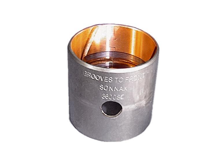
Oversized Rear Case Bushing 36008C
Fits '95-later units only. Late-style with 3 grooves to front.
- Bushing Style: Precision
- Material: Steel-backed bimetal
- Width: 1.620"
- Shaft Dia.: 1.470"
- Housing Bore: 1.624"
-
Helps cure:
- Damaged case
- Spun-out bushings
Required
Recommended
4R100 • E4OD
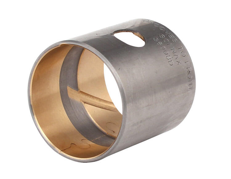
Rear Case Bushing 36008D
Fits '95-later units. Late-style with 3 grooves to front, 1 groove to back.
-
Helps cure:
- Premature wear & bushing failure
- Inadequate lubrication
Required
Recommended
F4A41/42/51 • F5A51 • R4/V4A51 • R5A51 • V5A51
Pump Bushing 41005-01
- Bushing Style: Precision
- Material: Steel-backed bimetal
- Shaft Dia.: 1.691"
- Width: 0.545"
- Housing Bore: 1.810"
-
Helps cure:
- Bushing wear
- Bushing failure
Required
Recommended
4F27E • FN4A-EL • FNR5 • FS5A-EL
Stator Bushing 46000-01K
- Bushing Style: Precision
- Material: Bimetal
- Housing Bore: 0.867"
- Shaft Dia.: 0.747"
- Width: 0.266"
-
Helps cure:
- High TCC slip RPM (TCCMACT) increases with operating temperature
- Code P0741
- Bushing failure
- Bushing wear
- Overheating
Required
Recommended
4L30-E • AR25 • AR35 • TH180C (3L30)
Bell Housing Bushing 54253-01
- Bushing Style: Precision
- Material: Steel-backed aluminum
- Width: 0.560"
- Shaft Dia.: 1.874"
- Housing Bore: 2.003"
-
Helps cure:
- Leaking front seal
- Bushing wear
Required
Recommended
722.6
Pump Bushing 68004-01
Fits '96-later
- Material: Bimetal
- Bushing Style: Precision
- Housing Bore: 1.810"
- Shaft Dia.: 1.692"
- Width: 0.550"
-
Helps cure:
- Bushing wear
- Bushing failure
Required
Recommended
722.6
Pump Bushing 68004-02
Finish-in-Place. Oversized O.D. Also fits 722.3 and 722.5 units.
- Material: Bimetal
- Bushing Style: Finish-in-Place
- Width: 0.550"
- Shaft Dia.: 1.678"
- Housing Bore: 2.000"
-
Helps cure:
- Bushing spins in housing
- Pump leaks
- Pump damaged
Required
Recommended
722.6
Input Shaft Bushing 68410-01
- Material: Bimetal
- Bushing Style: Precision
- Housing Bore: 1.023"
- Width: 0.446"
- Shaft Dia.: 0.906"
-
Helps cure:
- Bushing wear
- Bushing failure
Required
Recommended
722.6
Rear Pump Stator Bushing 68915-01
'96-Later
- Material: Bimetal
- Bushing Style: Precision
- Housing Bore: 1.358"
- Shaft Dia.: 1.239"
- Width: 0.420"
-
Helps cure:
- Bushing wear
- Bushing failure
Required
Recommended
CD4E • LA4A-EL
Reverse Clutch Drum Sleeve 73300-01
-
Helps cure:
- Damaged Reverse clutch drum journal
- Bushing failure
- Costly drum replacement
Required
Recommended
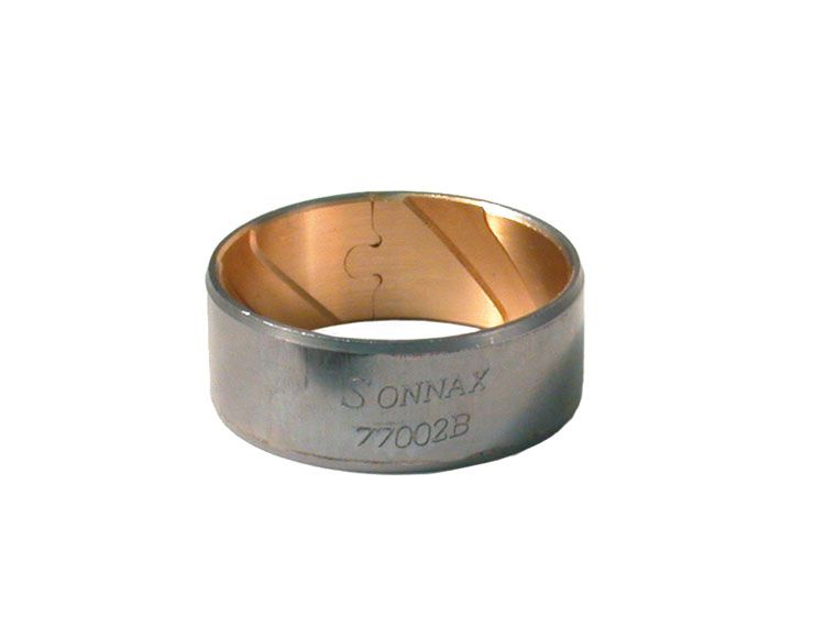
4L60 • 4L60-E • 4L65-E • 4L70-E
Rear Stator Support Bushing 77002B
Wider than OE
- Bushing Style: Precision
- Material: Steel-backed lead/bronze alloy
- Width: 0.510"
- Inner Dia.: 1.250"
- Housing Bore: 1.360"
- Shaft Dia.: 1.237"
-
Helps cure:
- Bushing wear
- Bushing failure
Required
Recommended
Required
Recommended
4L60 • 4L60-E • 4L65-E • 4L70-E
Wide Reaction Sun Gear Bushing 77010-01
May not work in some late-production sun gears with OE finish-in-place bushings.
- Material: Steel-backed bronze
- Bushing Style: Precision
- Housing Bore: 1.706"
- Shaft Dia.: 1.575"
- Width: 0.600"
-
Helps cure:
- Bushing failure
- Reaction carrier shaft damage
Required
Recommended
Required
Recommended

40TE • 40TES • 41AE • 41TE • 41TES • 42LE • 42RLE
Overdrive Clutch Hub Bushing 92004-L
Fits late-style hubs with shaft O.D. of 1.162" and housing bore of .937".
- Bushing Style: Precision
- Material: Steel-backed bimetal
- Inner Dia.: 0.837"
- Width: 1.141"
- Housing Bore: 0.937"
- Shaft Dia.: 0.835"
-
Helps cure:
- Planetary failure
- Shaft breakage
- Bushing failure
- Bushing wear
Required
Recommended
40TE • 40TES • 41AE • 41TE • 41TES • 42LE • 42RLE
Overdrive Clutch Hub Bushing 92004-LOS
Fits late-style hubs with shaft O.D. of 1.162" and housing bore of .941".
- Bushing Style: Precision
- Material: Steel-backed bimetal
- Inner Dia.: 0.841"
- Width: 1.141"
- Housing Bore: 0.941"
- Shaft Dia.: 0.839"
-
Helps cure:
- Planetary failure
- Shaft breakage
- Bushing failure
- Bushing wear
Required
Recommended
ZF6HP19 • ZF6HP21
Front Stator Support Bushing 95030-09
Fits .952" (24.17mm) diameter input shaft front journal. Not all ZF6HP19/21 units utilize a front stator support bushing; application must be verified before installation.
- Bushing Style: Precision
- Material: Bimetal, aluminum alloy lining
- Housing Bore: 1.063"
- Shaft Dia.: 0.952"
- Width: 0.393"
-
Helps cure:
- Bushing wear
- Bushing failure
- Damaged converter
Required
Recommended
MD 3000 Series
Pump Bushing S29524335
- Material: Bimetal
- Bushing Style: Precision
- Housing Bore: 2.517"
- Shaft Dia.: 2.246"
- Width: 0.680"
Required
Recommended
HD 4000 Series
Pump Bushing S29527102
Early-style
- Material: Bimetal
- Bushing Style: Precision
- Housing Bore: 2.944"
- Shaft Dia.: 2.625"
- Width: 0.700"
Required
Recommended
HD 4000 Series
Pump Bushing S29542029
Late-style
- Material: Bimetal
- Bushing Style: Precision
- Housing Bore: 2.878"
- Shaft Dia.: 2.623"
- Width: 0.700"
Required
Recommended
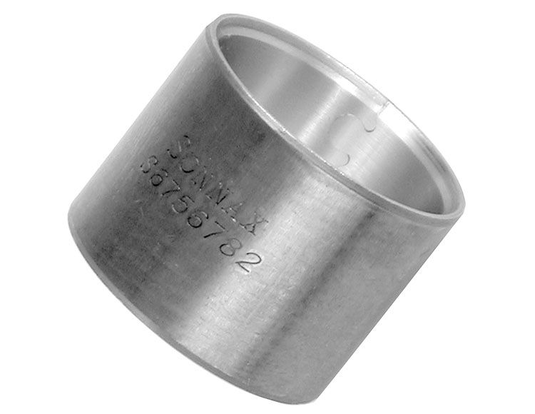
MT-600
Front Cover Bushing S6756782
- Bushing Style: Precision
- Material: Bimetal
- Housing Bore: 1.125"
- Width: 0.870"
- Shaft Dia.: 0.995"
Required
Recommended
6R80 (2009–2014) • 6R80 (2015-Later) • ZF6HP19 • ZF6HP26 • ZF6HP28
Input/Output Shaft Bushing 95030-05
Fits units with .669" (16.98mm) dia. shaft journals only.
- Bushing Style: Precision
- Material: Steel-backed alloy
- Housing Bore: 0.788"
- Shaft Dia.: 0.669"
- Width: 0.393"
-
Helps cure:
- Bushing wear
- Bushing failure
- Ratio codes
- B Clutch burned
Required
Recommended
ZF6HP26 • ZF6HP28
Sun Gear Shaft Bushing 95030-06
Fits units with .952" (24.17mm) dia. shaft journals only.
- Bushing Style: Precision
- Material: Steel-backed alloy
- Housing Bore: 1.063"
- Width: 0.393"
- Shaft Dia.: 0.952"
-
Helps cure:
- B Clutch burned
- Bushing wear
- Bushing failure
- Ratio codes
Required
Recommended
AT-540
Center Support Bushing S29506468
Fits AT-540/542/543/545/1542/1545.
- Material: Bimetal
- Bushing Style: Precision
- Housing Bore: 1.598"
- Shaft Dia.: 1.466"
- Width: 1.850"
-
Helps cure:
- 4th Clutch burned
- 4th Slip
- Bushing failure
- Bushing wear
- No 4th
- No Reverse
- Reverse slip
Required
Recommended
ZF6HP19 • ZF6HP26 • ZF6HP28
Rear Stator Support Bushing 95030-01
Fits 1.022" (25.97mm) dia. input shaft journal only.
- Bushing Style: Precision
- Material: Steel-backed alloy
- Width: 0.590"
- Housing Bore: 1.142"
- Shaft Dia.: 1.022"
-
Helps cure:
- E Clutch burned
- Gear ratio & solenoid codes
- Bushing wear
- Bushing failure
Required
Recommended
6R80 (2009–2014) • 6R80 (2015-Later) • ZF6HP26 • ZF6HP28
Rear Stator Support Bushing 95030-02
Fits 1.180" (29.96mm) dia. input shaft journal only.
- Bushing Style: Precision
- Material: Steel-backed alloy
- Housing Bore: 1.300"
- Shaft Dia.: 1.180"
- Width: 0.697"
-
Helps cure:
- E Clutch burned
- Gear ratio & solenoid codes
- Bushing wear
- Bushing failure
Required
Recommended
ZF6HP19 • ZF6HP26 • ZF6HP28
"A" Drum Front Bushing 95030-03
Fits 2.353" (59.77mm) diameter shaft journals only.
- Bushing Style: Precision
- Material: Steel-backed alloy
- Width: 0.315"
- Housing Bore: 2.481"
- Shaft Dia.: 2.353"
-
Helps cure:
- Bushing wear
- Bushing failure
Required
Recommended
ZF6HP19 • ZF6HP26 • ZF6HP28
"A" Drum Rear Bushing 95030-04
Fits 1.967" (49.97mm) dia. shaft journals only.
- Bushing Style: Precision
- Material: Steel-backed alloy
- Housing Bore: 2.088"
- Shaft Dia.: 1.967"
- Width: 0.307"
-
Helps cure:
- Bushing wear
- Bushing failure
Required
Recommended
6R80 (2009–2014) • ZF6HP26 • ZF6HP28
"B"/Direct Clutch Bushing 95030-07
Fits units with 1.337" (33.97mm) dia. shaft journals only.
- Bushing Style: Precision
- Material: Steel-backed alloy
- Housing Bore: 1.457"
- Shaft Dia.: 1.337"
- Width: 0.465"
-
Helps cure:
- Bushing wear
- Bushing failure
- B Clutch burned
- Direct clutch burned
- Ratio codes
Required
Recommended
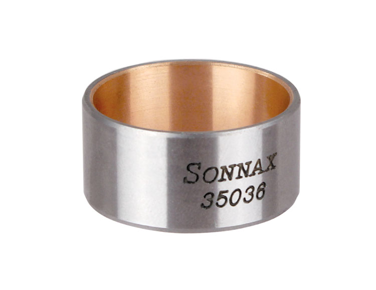
845RE • 850RE • ZF8HP45 • ZF8HP50 • ZF8HP55 • ZF8HP70 • ZF8HP75
Front Stator Support Bushing 35036
- Bushing Style: Precision
- Material: Steel-Backed Alloy
- Housing Bore: 1.205"
- Shaft Dia.: 1.085"
- Width: 0.591"
-
Helps cure:
- Bushing wear
- Bushing failure
- Harsh downshifts
- TCC apply & release concerns
- Harsh TCC apply
Required
Recommended
ZF6HP26 • ZF6HP28
Bushing Kit 95030-26K
Fits units with input shaft bushing journal diameters of 1.022" (25.97mm) & 1.180" (29.96mm).
- Bushing Style: Precision
- Material: Steel-backed alloy
-
Helps cure:
- E Clutch burned
- B Clutch burned
- Gear ratio & solenoid codes
- Bushing wear
- Bushing failure
While Sonnax makes every effort to ensure the accuracy of technical articles at time of publication, we assume no liability for inaccuracies or for information which may become outdated or obsolete over time.